
Thrust bearing for a shaft, particularly for the shaft of a water turbine

A technology for thrust bearings and bearing rings, applied to shafts and bearings, rotating bearings, bearings, etc., can solve the problems of continuous damage, vulcanization damage, loss of elasticity, etc., and achieve the effect of simple manufacturing method and prevention of damage

Active Publication Date: 2012-09-19
VOITH PATENT GMBH
View PDF1 Cites 0 Cited by
  • Summary
  • Abstract
  • Description
  • Claims
  • Application Information

AI Technical Summary

Problems solved by technology

Here it can lose its elasticity so that it is permanently damaged by itself
May also cause damage to the vulcanization between the lamellar spring element and the bearing ring

Method used


Image

  • Thrust bearing for a shaft, particularly for the shaft of a water turbine
  • Thrust bearing for a shaft, particularly for the shaft of a water turbine
  • Thrust bearing for a shaft, particularly for the shaft of a water turbine

Examples


Embodiment Construction

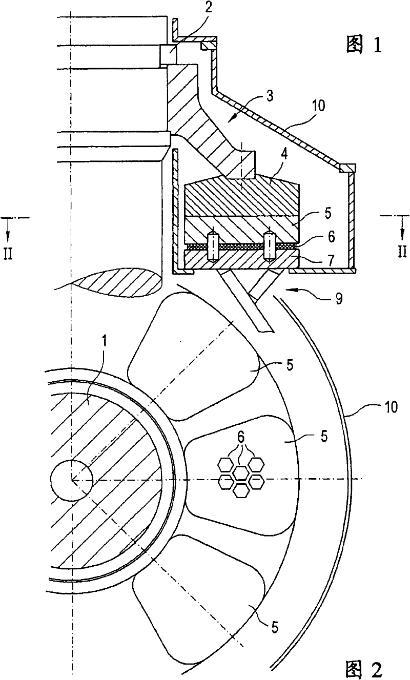
[0024] exist figure 1 Shaft 1 with vertical axis 1.1 can be seen in . This shaft is surrounded by a collar 2 . The collar 2 is supported by a collar sleeve 3 which surrounds the shaft 1 . The lower end of the collar sleeve 3 rests on a thrust ring 4 which likewise surrounds the shaft 1 . The thrust ring 4 itself rests itself on a plurality of bearing seats 5 which are arranged at regular intervals around the shaft 1 .

[0025] The spring element 6 follows. These spring elements rest on the bearing ring 7 . The pins 8 engage in the bores of the bearing seat 5 and of the bearing ring 7 . The bearing structure 9 supports the bearing ring 7 . The housing 10 surrounds the collar 2 , the collar sleeve 3 , the thrust collar 4 , the bearing seat 5 , the spring element 6 and the bearing ring 7 .

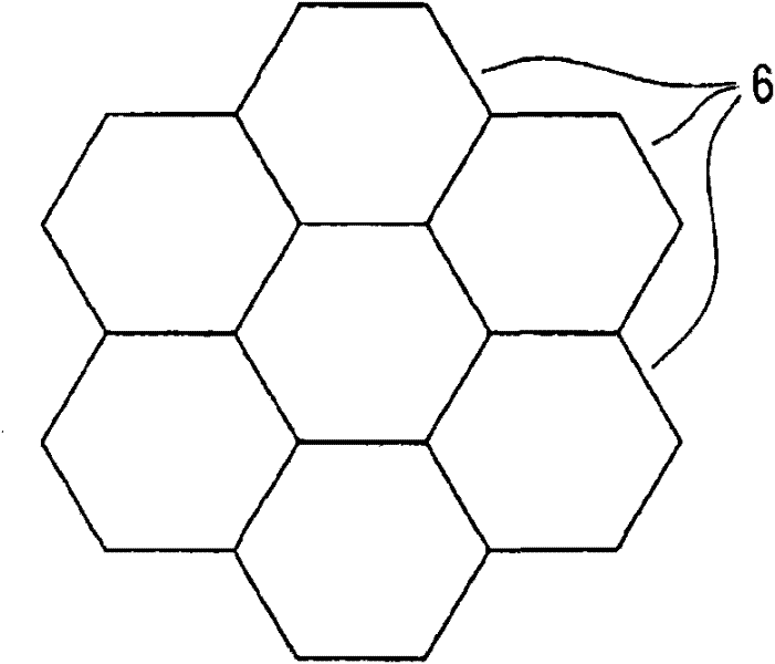
[0026] exist figure 2 The configuration of the spring element is explicitly shown in . As can be seen here are hexagonal flakes.

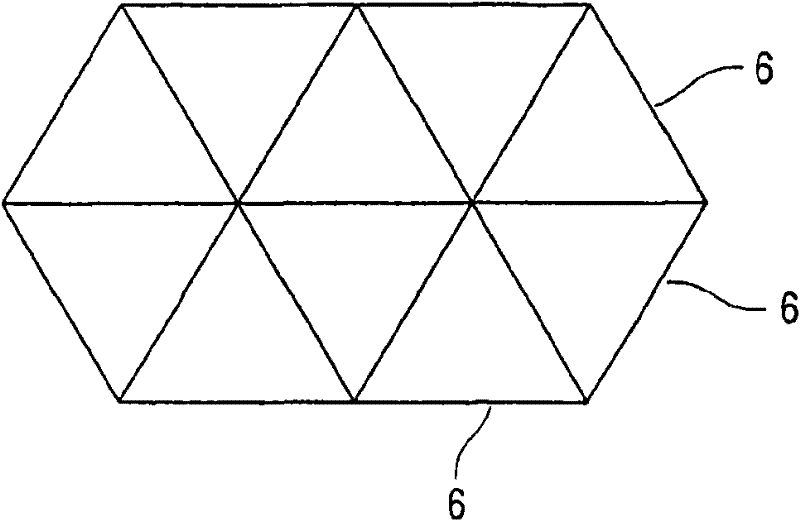
[0027] The spring elements do not necessarily hav...


PUM


Abstract

The invention relates to an axial bearing for absorbing high axial loads of a shaft having a bearing ring (7) that comprises a central bore for inserting the shaft (1) and is supported on a fixed base (9); having a plurality of spring elements (6) made of elastic material attached to the bearing ring (7); having a load transmission device (3) for transferring the load from the shaft (1) to the spring elements (6). The invention is characterized by the following features: the spring elements (6) are elastic bodies that may be joined to one another or inserted into one another like puzzle pieces in a form-fitting manner; the contours of the spring elements (6) are structured such that no gap remains between adjacent spring elements, at least beginning at a certain load.

Description

technical field [0001] The invention relates to a thrust bearing for absorbing high axial loads. Background technique [0002] Bearings of this type are used, for example, in water turbines or pumps with vertical shafts. [0003] Such a thrust bearing is described, for example, in DE 26 26 609 C3. [0004] The bearing basically comprises: a shaft, a collar, a collar sleeve and a thrust ring as rotating parts in the axial magnetic flux direction; and a bearing seat, a spring element, a bearing ring and a bearing structure as supporting upright parts. In order to be able to adjust the hydrodynamic lubricating oil film between the thrust ring and the housing during operation on all bearing housings, the spring element in the support must be able to allow the bearing housing to be turned over and the manufacturing tolerances and likewise the installation tolerances All are compensated by the axial elastic force. In order to ensure sufficient spring force in known thrust beari...

Claims


Application Information

Patent Timeline
Patent Type & Authority Patents(China)
IPC IPC(8): F03B11/06F16C17/04F16C27/06F16C27/08
CPCY02E10/226F16C27/063F16C27/08F03B11/066F05B2280/5001F16C17/04F05D2260/36F05C2251/02Y10T29/49609Y02E10/20
Inventor 迈克尔·博滕沙因
Owner VOITH PATENT GMBH
Learn More