
Wave-powered generating device

A technology of wave power generation and power generation system, which is applied in ocean energy power generation, engine components, machines/engines, etc., can solve the problems of inability to utilize ocean wave energy, inability to achieve continuous work, and large investment in civil engineering and electromechanical engineering. Simple structure and low manufacturing cost

Inactive Publication Date: 2010-07-07
OCEAN UNIV OF CHINA
View PDF0 Cites 14 Cited by
  • Summary
  • Abstract
  • Description
  • Claims
  • Application Information

AI Technical Summary

Problems solved by technology

[0003] Tidal power generation is a clean and renewable energy source, but its civil engineering investment is large, the cost is high, and maintenance is difficult. The tidal range and water head often change in a day and are intermittent. At the same time, the energy generated by waves cannot be used. Energy utilization relatively low rate
In order to develop and utilize the huge energy stored by ocean waves, people have done a lot of discussion and research on ocean wave power generation, and various types of wave generators have appeared. However, the current wave generators have relatively small power generation capacity and cannot achieve continuous work. , cannot meet the actual needs

Method used


Image

  • Wave-powered generating device
  • Wave-powered generating device
  • Wave-powered generating device

Examples


Embodiment Construction

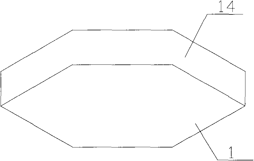
[0018] Such as figure 1 As shown, the device comprises a casing 1 anchored to the seabed. Two floating ball power generation systems a and b are arranged in the casing 1, and the two systems are installed on the same rotating shaft 7. The floating ball power generation system includes a torsion spring, a ratchet mechanism and a transmission wheel. The ratchet mechanism includes a ratchet 4 and a small flywheel 5. The ratchet 4 is box-shaped, and the small flywheel 5 is installed in the ratchet 4. There is a ratchet on the inner circumference of the ratchet 4 41, the small flywheel 5 is fixedly installed on the rotating shaft 7 through the key 12, and the ratchet 41 can produce a braking effect on the small flywheel 5. The ratchet 4 is mounted on the rotating shaft 7 through a hole on its sealing side, but since the diameter of the hole on the sealing side is larger than that of the rotating shaft 7, the ratchet 4 does not rotate with the rotating shaft 4. The sealing side of...


PUM


Abstract

The invention relates to a wave-powered generating device belonging to the field of hydraulic machinery or hydraulic generators, and aims to provide a device for continuously generating electricity by utilizing waves. The wave-powered generating device comprises a shell which is anchored on seabed; floating ball generating systems are arranged in the shell and mounted on a rotating shaft; the system comprises a spring, a ligament, a ratchet wheel mechanism and a transmission wheel, wherein the ratchet wheel mechanism comprises a small flywheel and a ratchet wheel; the small flywheel and the transmission wheel are fixedly mounted on the rotating shaft; the transmission wheel drives a gear in a gearbox to rotate; the ratchet wheel is in a box shape; the small flywheel is arranged in the ratchet wheel; a pawl is arranged on the inner circumferential surface of the ratchet wheel; the outer circumferential surface is wound by the ligament, one end of which is fixed on the ratchet wheel; and the other end is connected with the floating ball which is arranged on the exterior of the shell; the sealing side of the ratchet wheel is connected with the spring which is wound on the rotating shaft; the other end of the spring is fixed; and the shell is internally provided with at least two floating ball generating systems. The invention has simple structure, convenient use, strong wave resistance, low manufacture and construction costs and long-term use without manual maintenance.

Description

technical field [0001] The invention relates to a hydraulic machine or a hydraulic engine, in particular to a power generating device which fixes some components on the seabed and uses waves as the driving force. Background technique [0002] The vast ocean contains huge energy. At present, many tidal power generation devices are to build water retaining dams in bays or tidal estuaries to form reservoirs, and place hydroelectric generators in or beside the dams to utilize sea water levels during tidal fluctuations. When the seawater passes through the turbine, it drives the hydroelectric generating set to generate electricity, that is, the potential energy and kinetic energy of seawater are used to convert it into electrical energy through the hydroelectric generator. [0003] Tidal power generation is a clean and renewable energy source, but its civil engineering investment is large, the cost is high, and maintenance is difficult. The tidal range and water head often change...

Claims


Application Information

Patent Timeline
Patent Type & Authority Applications(China)
IPC IPC(8): F03B13/16
CPCY02E10/38Y02E10/30
Inventor 刘贵杰张开升张庆力
Owner OCEAN UNIV OF CHINA
Learn More