Coal anaerobic drying device and drying system

A drying device and drying system technology, used in heating devices, drying solid materials, heating to dry solid materials, etc., can solve the problems of large power consumption and high drying costs, reduce emissions, overcome severe wear of heat exchangers, reduce The effect of energy consumption

Inactive Publication Date: 2010-06-30
郑州拉姆顿清洁能源工程技术有限公司
View PDF0 Cites 8 Cited by
  • Summary
  • Abstract
  • Description
  • Claims
  • Application Information

AI Technical Summary

Problems solved by technology

Due to the problem of large power consumption in fluidized bed drying, the drying cost of the third-generation drying method is relatively high

Method used


Image

  • Coal anaerobic drying device and drying system
  • Coal anaerobic drying device and drying system
  • Coal anaerobic drying device and drying system

Examples


Embodiment 1

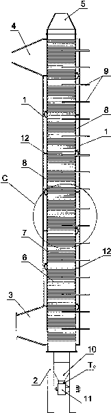
[0052] Embodiment one: see figure 1 , Picture 1-1 , Figure 1-2 , Figure 1-3 , a coal anaerobic drying device, comprising a vertical drying cylinder 7, the upper and lower ends of the drying cylinder 7 are respectively provided with a coal inlet 5 and a coal outlet 10, and the upper part of the drying cylinder 7 is fixedly equipped with an air outlet pipe 17, The lower part or the middle part is fixedly equipped with an intake pipe 16 .

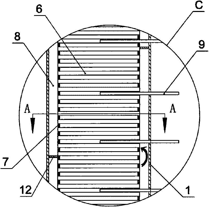
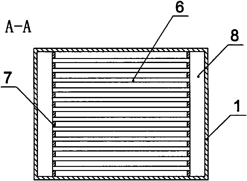
[0053] On the outside (in the vertical direction) of the opposite side walls of the vertical drying cylinder 7 (left and right), there are hot air chambers 8 that are isolated from the drying cylinder 7 and independent from each other, and between the two independent hot air chambers 8 A certain number of row pipes 6 are connected.

[0054] A certain number of transverse partitions 12 are arranged in the two adjacent hot gas chambers 8 up and down, so that the hot gas chamber is divided into multiple independent hot gas chambers from to...

Embodiment 2

[0058] Embodiment two: see figure 2 , diagram 2-1 , Figure 2-2 , Figure 2-3 , Figure 2-4 , the numbering is the same as that of Embodiment 1, the meaning is the same, the same parts will not be repeated, and the difference is: change the row of pipes as follows Figure 2-3 The row plate 24.

Embodiment 3

[0059] Embodiment three: see image 3 , Figure 3-1 , the numbering is the same as in Embodiment 1, the meaning is the same, the same parts will not be repeated, the difference is: the air inlet pipe 16 is located in the middle of the drying cylinder 7, and the hot gas flow sequence is deflected downward from the hot air chamber in the middle of the drying cylinder and discharged, and then passes through The hot air chamber at the bottom of the drying cylinder leads upwards to the return pipe 25 for the flue gas to communicate with the hot air chamber above the inlet pipe 16 , and then deflects upwards in sequence, and finally flows to the air outlet pipe 17 . This embodiment is suitable for drying the surface water of ordinary coal or lignite, and of course it is also suitable for drying chemical industry, metal and non-metallic minerals, etc.


PUM

PropertyMeasurementUnit
heating valueaaaaaaaaaa

Abstract

The invention relates to a coal anaerobic drying device and a drying system. The device comprises a vertical drying cylinder, a coal inlet, a coal outlet, an air inlet pipe and an air outlet pipe, wherein hot air cavities are respectively arranged outside two lateral walls of the drying cylinder; a certain number of array pipes or array plates are communicated between the two hot air cavities so as to ensure that coal in the drying cylinder and hot air in the hot air cavities and hot air in the array pipes or array plates are completely isolated; a steam pipe arranged inside the drying cylinder is extracted outside the drying device; the coal anaerobic drying system comprises the coal anaerobic drying device and a heating system, wherein a thermometer T1 and a thermometer T2 are arranged at the air inlet pipe port and the air outlet pipe port respectively; a discharge valve and a thermometer T0 are arranged at the discharge port. By controlling the temperature, the device and the system are applicable to both the drying of common coal and coal slime and the drying and upgrading of brown coal, not only can extract surface moisture of the brown coal, but also can remove partial bound water, transforms the brown coal from soft coal to hard coal, transforms the brown coal from hydrophily to hydrophobicity, are convenient for transportation, storage and use, and are favorable to popularization and implementation.

Description

1. Technical field: [0001] The invention relates to a coal drying and modification technology, in particular to a coal anaerobic drying device and a drying system. 2. Background technology: [0002] According to statistics, the world's lignite reserves are about 2622.9 billion tons, accounting for about 24.4% of the world's total coal reserves. China has discovered lignite resources of 129.132 billion tons, accounting for about 12.7% of China's coal reserves. Because lignite is formed very shallow from the surface, it is suitable for open-pit mining, so it is cheap. But lignite also has the following outstanding problems: [0003] 1. High moisture and low calorific value. Lignite generally has a moisture content between 30% and 65%, and its general calorific value is about 3000kcal / kg. [0004] 2. Low density, easy weathering, spontaneous combustion when exposed to water, and the sales radius does not exceed 500 kilometers. [0005] In order to solve the above problems, ...

Claims


Application Information

Patent Timeline
Patent Type & Authority Applications(China)
IPC IPC(8): F26B17/12F26B3/18F26B23/10C10L5/00
Inventor 黄龙李英群查理德·迪玻特克里斯托夫·摩豪斯
Owner 郑州拉姆顿清洁能源工程技术有限公司
Why Eureka
Try Eureka