Eureka AIR delivers breakthrough ideas for toughest innovation challenges, trusted by R&D personnel around the world.

Construction method and equipment of holding and pressing type static-pressure driven cast-in-place pile

A technique of sinking tubular piles and static pressure, applied in the direction of sheet pile walls, foundation structure engineering, building construction, etc., can solve the problem of large vibration force, noise and oil smoke pollution, damage to the soil structure of the pile body, and affect adjacent buildings Object safety and surrounding ecological environment and other issues, to achieve the effect of shortening auxiliary working hours, flexible movement, and improving work efficiency

Inactive Publication Date: 2010-06-30
赵黎明
View PDF0 Cites 12 Cited by
  • Summary
  • Abstract
  • Description
  • Claims
  • Application Information

AI Technical Summary

Problems solved by technology

The defects of the construction method and equipment of the existing top-pressure concrete immersed pipe pouring pile are: because these methods and equipment will produce a lot of vibration force, noise and oil smoke pollution during the construction process, destroy the soil structure around the pile body, Affect the safety of adjacent buildings and the surrounding ecological environment

Method used


Image

  • Construction method and equipment of holding and pressing type static-pressure driven cast-in-place pile
  • Construction method and equipment of holding and pressing type static-pressure driven cast-in-place pile
  • Construction method and equipment of holding and pressing type static-pressure driven cast-in-place pile

Examples


Embodiment Construction

[0018] The present invention is further described as follows in conjunction with specific embodiment:

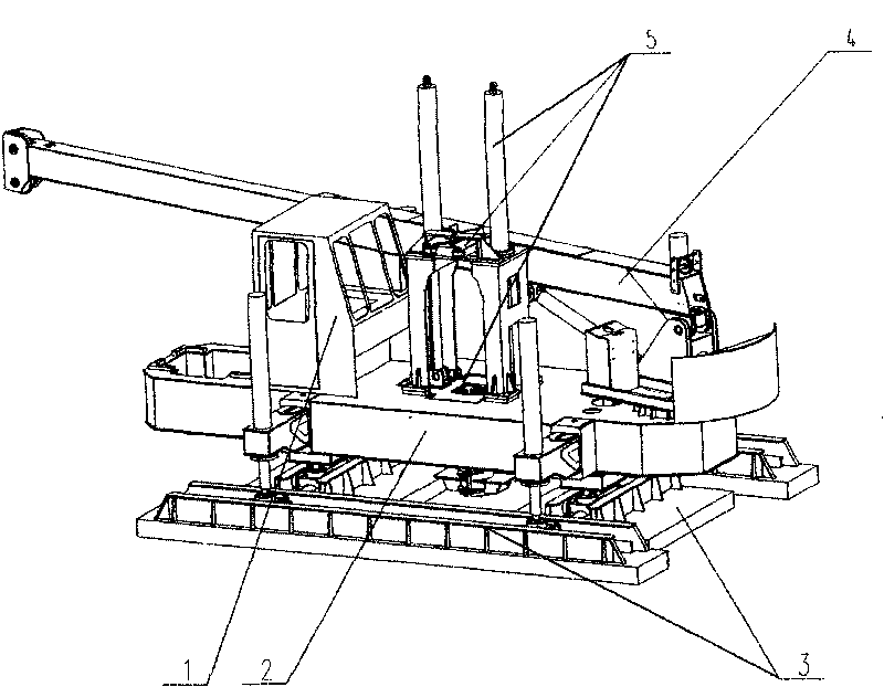
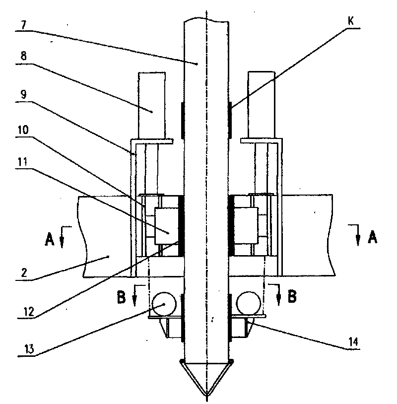
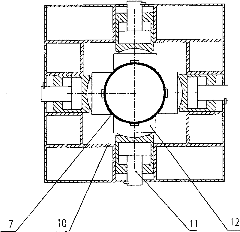
[0019] A construction method of pressure-holding static pressure pipe-sinking pile. The equipment used in the method is a pressure-holding static pressure pipe-sinking pile machine. For its overall structure, see the attached figure 1 , mainly including the operating device 1, the fuselage 2, the running mechanism 3, the pile hanging mechanism 4, and the pile clamping and pile pressing mechanism 5, the pile clamping and pile pressing mechanism 5 is a side-hugging pile clamping and pile pressing mechanism, see the attached figure 2 , it is vertically fixed on the fuselage 2 by the pile-pressing frame 9, and the inside of the pile-pressing frame 9 has a vertical slide rail, and the slide rail is equipped with a pile clamping box 10 that slides up and down along the slide rail, and the pile-pressing frame 9 passes through the pile-pressing oil cylinder. 8 is connected with the...


PUM


Abstract

The invention relates to a construction method of a holding and pressing type static-pressure driven cast-in-place pile by adopting a holding and pressing type static-pressure immersed tube pile machine. The machine comprises a machine body, a pile hanging mechanism, a walking mechanism, a control device and a side holding type pile clamping and pressing mechanism, wherein the side holding type pile clamping and pressing mechanism is connected with a pile clamping box sliding up and down along a slide rail through a pile pressing oil cylinder by a pile pressing frame, a pile clamping oil cylinder is arranged in the pile clamping box and connected with a clamping block for clamping a pile tube, and the pile clamping box is elastically connected with a concrete jolt ramming mechanism. The construction method comprises the following steps of: immersing the pile tube to an underground designed elevation part in a holding and pressing mode from the side face of the pile tube; primarily pouring concrete to an elevation part at the bottom of a reinforcing steel bar cage; then putting the reinforcing steel bars into a pile tube hole; and pouring concrete to the top of the reinforcing steel bar cage, wherein during pulling the pile tube, the concrete in the pile hole is jolt rammed while the pile tube is pulled. The invention has the advantages of no vibration, no noise and no oily fume environmental pollution, and the length of the pile tube is not limited by the height of the pile pressing frame.

Description

technical field [0001] The invention relates to a concrete pile construction method and its construction machinery in building foundation engineering technology, in particular to a construction method and equipment for a pressure-holding static pressure sinking pipe grouting pile Background technique [0002] In deep foundation projects all over the world, pile foundation is the main means, and concrete pouring pile is the most widely used in pile foundation. Cast-in-situ piles can adapt to changes in various strata without pile connection, can bear large vertical loads, and can also withstand large horizontal loads, and can be embedded in the ground to a certain depth, with good seismic performance and small settlement , can prevent uneven settlement. In the known technology, the existing concrete sinking pipe pile usually adopts the construction method of top pressure hammering, vibration or vibration impact. The corresponding equipment adopts the top-pressure rolling tu...

Claims


Application Information

Patent Timeline
Patent Type & Authority Applications(China)
IPC IPC(8): E02D11/00E02D5/38E04G21/06
Inventor 赵黎明欧阳立志欧阳烽李映原苏慧李忠平
Owner 赵黎明
Why Eureka
Eureka Blog
Learn More