
Electromagnetic energy selection surface

A technique for selecting surfaces, electromagnetic energy, applied in the direction of electrical components, magnetic/electric field shielding, etc., capable of solving problems such as structures or materials that have not yet been retrieved

Active Publication Date: 2010-06-23
CHENGDU FOURIER ELECTRONICS TECH
View PDF0 Cites 21 Cited by
  • Summary
  • Abstract
  • Description
  • Claims
  • Application Information

AI Technical Summary

Problems solved by technology

No structures or materials have been retrieved for this function

Method used


Image

  • Electromagnetic energy selection surface
  • Electromagnetic energy selection surface
  • Electromagnetic energy selection surface

Examples


Embodiment Construction

[0012] The specific implementation manners of the present invention will be further described in detail below in conjunction with the accompanying drawings.

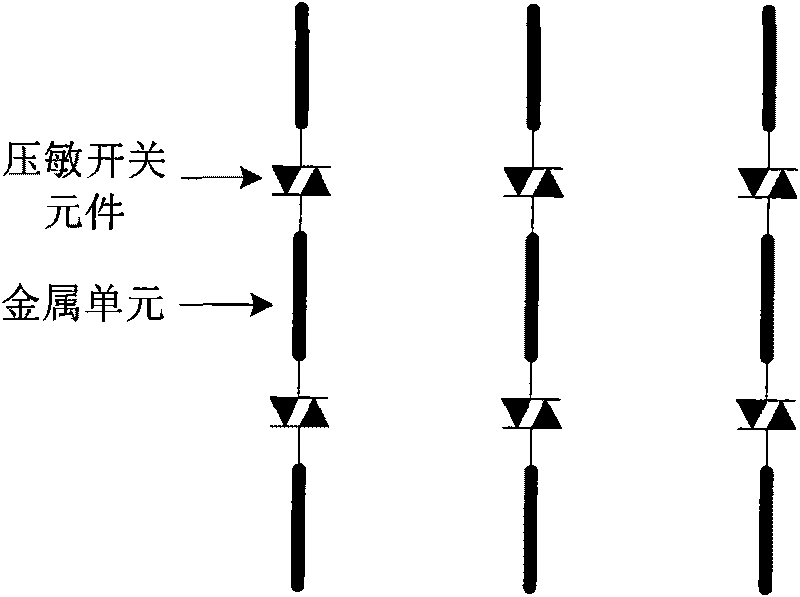
[0013] figure 1 It is a schematic structural diagram of Embodiment 1 of an electromagnetic energy selective surface provided by the present invention. The electromagnetic energy selection surface provided by this embodiment can protect against vertically polarized electromagnetic pulses. Several "1"-shaped metal units and several pressure-sensitive switch elements arranged at appropriate intervals in several meridian directions are connected alternately with each other. The spacing is less than one-tenth of the wavelength of the electromagnetic pulse.

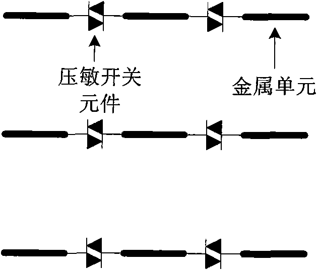
[0014] figure 2 It is a schematic structural diagram of Embodiment 2 of an electromagnetic energy selective surface provided by the present invention. The electromagnetic energy selection surface provided by this embodiment can protect against horizontally polarized e...


PUM


Abstract

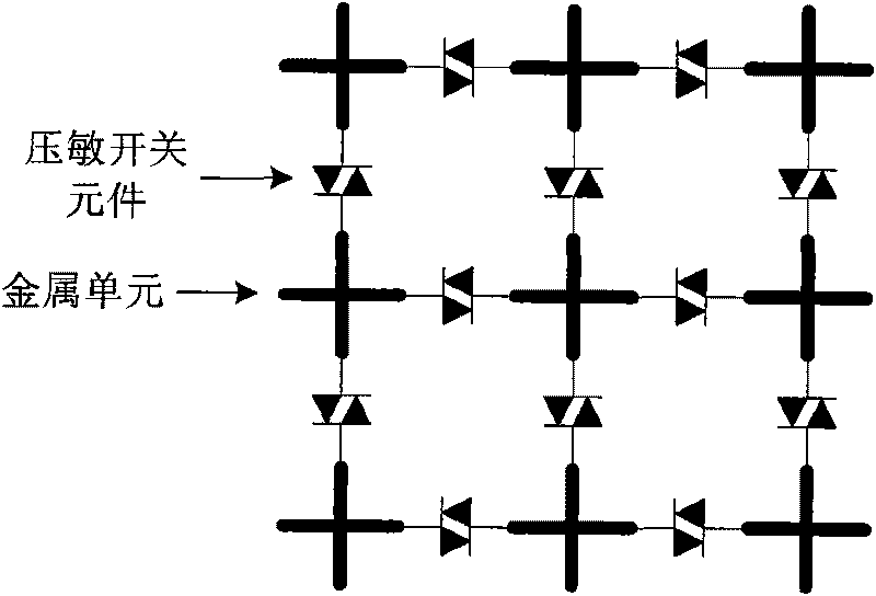
The invention aims to design an electromagnetic energy selection surface with electromagnetic energy low-pass property, which transmits low-energy electromagnetic signals to shield high-energy electromagnetic pulse. The invention adopts the technical scheme that the electromagnetic energy selection surface consists of metal units and pressure sensitive switch elements which are alternately connected with each other in the warp or / and weft directions. The metal units can be crossed metals or straight metals, which are determined by the polarization form of the electromagnetic pulse.

Description

technical field [0001] The invention relates to a strong electromagnetic pulse protection technology, which can be applied to the electromagnetic pulse protection of antennas or electronic information systems. Background technique [0002] Modern electronic information systems generally include sophisticated and advanced electronic computers, semiconductor integrated circuits, and weak current control software. The more electronic the system is, the more sensitive it is to changes in electromagnetic fields, voltages, and currents in the surrounding environment. Studies and experiments have shown that strong electromagnetic pulses can burn out the semiconductor insulating layer or integrated circuits of electronic equipment, resulting in equipment failure or permanent damage, resulting in huge economic losses. Strong electromagnetic pulse poses a huge threat to the information society that increasingly relies on electronic equipment. How to effectively protect the safe and r...

Claims


Application Information

Patent Timeline
Patent Type & Authority Applications(China)
IPC IPC(8): H05K9/00
Inventor 刘培国万双林李高升周东明刘继斌何建国
Owner CHENGDU FOURIER ELECTRONICS TECH
Learn More