Inductor improved structure

An improved structure and inductor technology, applied in transformer/inductor magnetic core, inductor/transformer/magnet manufacturing, inductor with magnetic core, etc., can solve problems such as vibration and noise, improve time, speed up production process, The effect of avoiding human error

Inactive Publication Date: 2010-06-23
LOGAH TECH CORP
View PDF0 Cites 1 Cited by
  • Summary
  • Abstract
  • Description
  • Claims
  • Application Information

AI Technical Summary

Problems solved by technology

[0006] Another object of the present invention is to provide an improved structure of inductors, which can solve the problems of vibration noise and eddy current loss when using existing inductors, so as to maintain the stability of electronic products during use and improve the service life

Method used


Image

  • Inductor improved structure
  • Inductor improved structure
  • Inductor improved structure

Examples


Embodiment

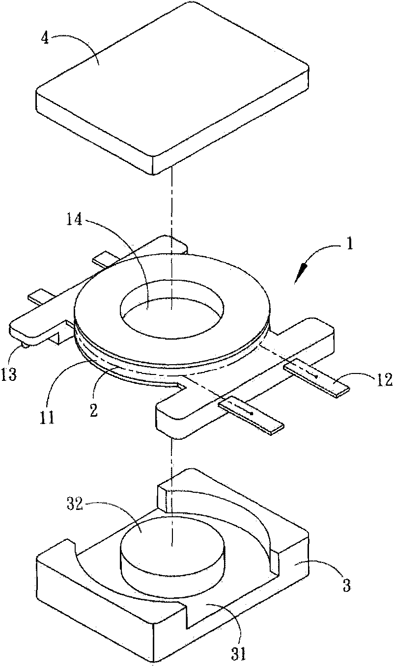
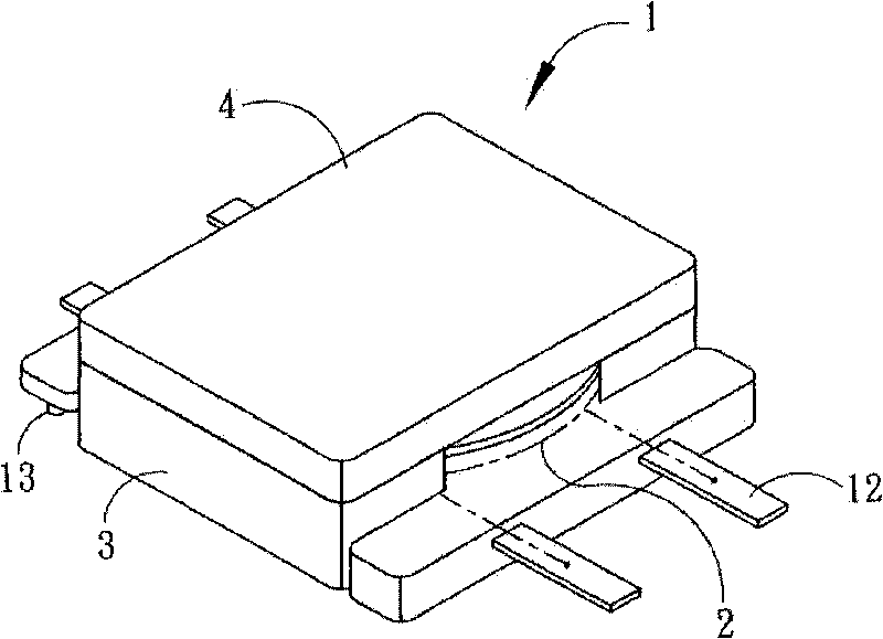
[0026] see Figure 1 to Figure 3 A modified structure of an inductor is shown, mounted on a circuit board 5 . The inductor mainly includes a wire frame 1 , a coil 2 , an iron core 3 and a cover 4 .

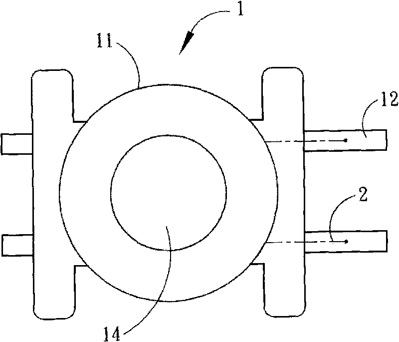
[0027] The wire frame 1 is made of insulating material, such as plastic molding. A winding area 11 is arranged in the bobbin frame 1 , and the winding area 11 is designed in a horizontal ring, so as to provide the coil 2 to be wound horizontally in a ring. Terminals 12 are arranged around the wire frame 1 , and the two ends of the coil 2 are connected to the terminals 12 to generate an inductance function. A positioning rod 13 is further arranged around the wire frame 1 , and the positioning rod 13 is used for fast positioning on the circuit board 5 .

[0028] The iron core 3 is provided with a slot 31, and a boss 32 is arranged in the slot 31, and a perforation 14 is arranged in the center of the wire frame 1 surrounded by the coil 2, so that the wire frame 1 is sleeved on the...


PUM


Abstract

The invention relates to an inductor improved structure. The inductor improved structure comprises a coil holder, a coil, an iron core and a cover, wherein terminals are arranged near the coil holder, the wire of the coil is wound on the periphery of the coil holder, the two ends of the coil are connected with the terminals; a locating rod is arranged near the coil holder and is used to fast position the coil holder on a circuit board; the iron core is provided with a notch, a convex cylinder is arranged in the notch, a through hole is arranged on the convex cylinder opposite to the centre of the coil holder to ensure that the coil holder is sleeved on the convex cylinder through the through hole, the coil holder can be fixed by the notch; and the cover is arranged on the upper end of the coil holder and fits with the iron core to cover the coil. The inductor formed by the above steps is arranged in a holding hole on the surface of the circuit board, and a locating hole is arranged on a circuit board opposite to the outside of the holding hole to ensure that the locating rod can be inserted in the locating hole for quick positioning. Therefore, the inductor improved structure can be used to ensure that the inductor can be quickly and accurately positioned on the circuit board and the terminals are near the circuit board so that the welding and processing operations of the terminals can become convenient.

Description

technical field [0001] The invention relates to an improved structure of an inductor. Background technique [0002] Existing inductor structures such as Figure 6 , Figure 7 As shown, it includes a wire frame 6 on which a coil 7 is wound. Both ends of the coil 7 are connected to terminals 61 around the wire frame 6 . And the wire frame 6 is pierced with an iron core 8 so that the coil 7 surrounds the periphery of the iron core 8 to generate an inductance function. This inductor is generally used in the field of DC / DC conversion circuits or AC / AC conversion circuits, but not in the field of ACsaDC conversion. [0003] However, the aforementioned existing inductor is affected by its structure, and its manufacturing process is more complicated and its cost is higher. Moreover, the conventional inductor usually has a large volume, which makes it difficult to assemble, especially for electronic products that are increasingly miniaturized. However, the positioning of the term...

Claims


Application Information

Patent Timeline
Patent Type & Authority Applications(China)
IPC IPC(8): H01F17/04H01F27/30H01F27/24H01F41/06H01F41/098
Inventor 吕志平姜智森
Owner LOGAH TECH CORP
Why Eureka
Try Eureka