
Panel pressing detection device and pressing mechanism

A detection device and panel technology, applied in nonlinear optics, instruments, optics, etc., can solve problems such as easy loopholes, eye fatigue of inspectors, and difficulty in precise control of power, so as to improve inspection quality and solve manpower and safety problems , to avoid the effect of destruction

Inactive Publication Date: 2010-06-23
UTECHZONE CO LTD
View PDF0 Cites 21 Cited by
  • Summary
  • Abstract
  • Description
  • Claims
  • Application Information

AI Technical Summary

Problems solved by technology

When the dead point exceeds the above standard, it will be regarded as a substandard or defective product, which will affect the price of the LCD panel. Therefore, the dead point test is generally carried out before shipment.
[0004] The above-mentioned dead pixels are particularly easy to appear when the liquid crystal display panel is lightly pressed, so at present, a method of manually detecting the dead pixels of the liquid crystal display panel is to drive the liquid crystal display panel, and then the inspector presses the liquid crystal display panel with fingers to prompt the bad spots Points appear, and then use the naked eye to judge
[0005] However, due to the difficulty of precise control of the force of finger pressing, sometimes the LCD panel will be damaged, and it is impossible to systematically press the inspection. It can only be carried out by random inspection, which consumes a lot of manpower, and the inspection quality cannot be effectively controlled; in addition, the naked eye inspection is easy. If loopholes occur, long-term naked eye observation will also cause eye fatigue of the inspector, making detection errors more likely to occur. Furthermore, the inspector must be quite close to the production line equipment of the LCD panel, which also poses safety concerns

Method used


Image

  • Panel pressing detection device and pressing mechanism
  • Panel pressing detection device and pressing mechanism
  • Panel pressing detection device and pressing mechanism

Examples


Embodiment Construction

[0034] The foregoing and other technical contents, features and effects of the present invention will be clearly presented in the following detailed description of preferred embodiments with reference to the accompanying drawings.

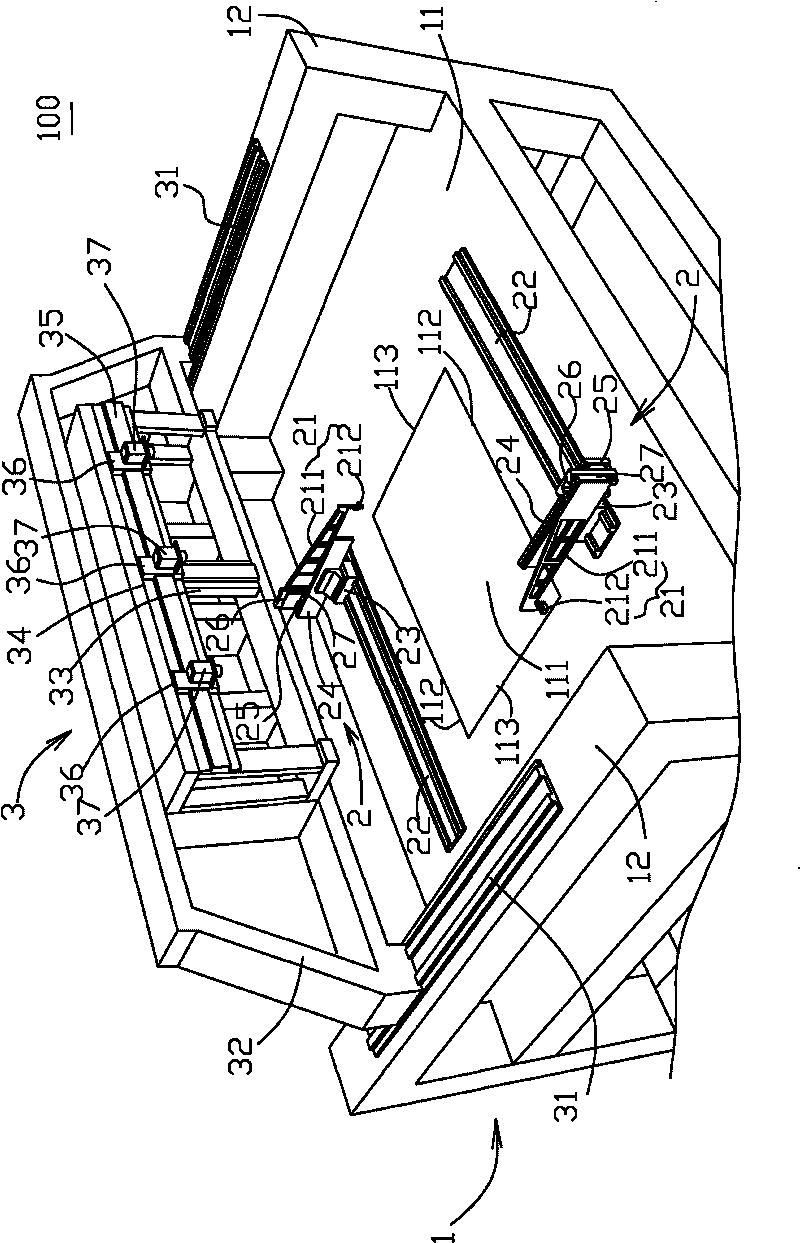
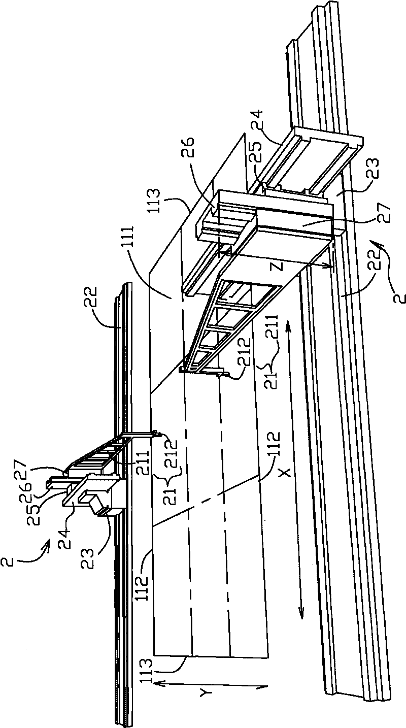
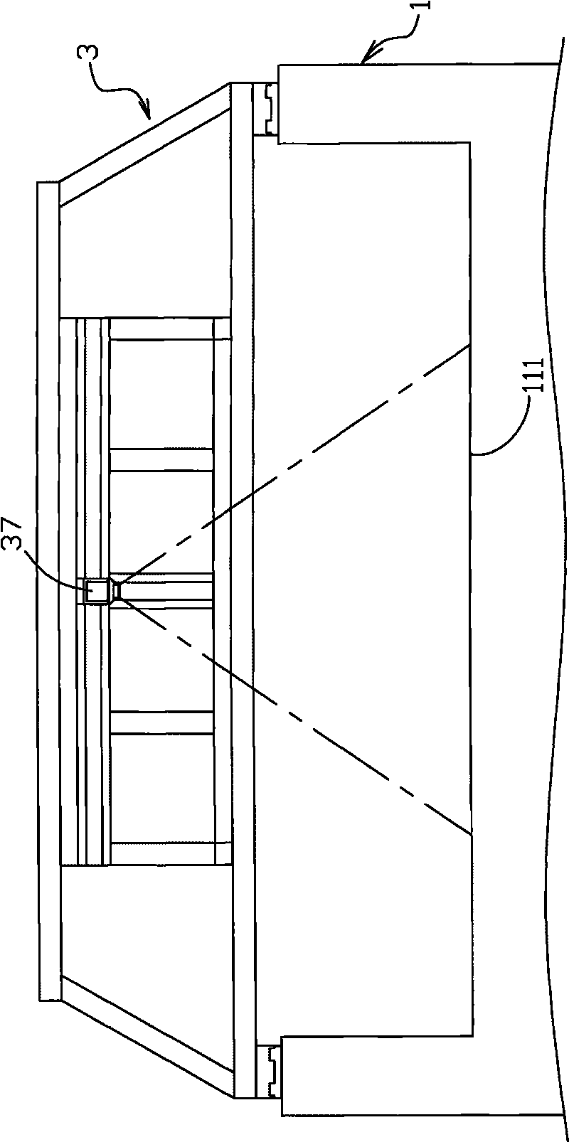
[0035] figure 1 and figure 2 Shown is a preferred embodiment of the panel pressing detection device 100 of the present invention, the panel pressing detection device 100 is suitable for detecting a driven liquid crystal display panel (not shown), and includes a machine 1, two pressing mechanisms 2 and An imaging unit 3 .

[0036] The machine 1 includes a testing platform 11 for placing the panel, and two racks 12 respectively extending upward from both sides of the testing platform 11 . There is a panel accommodating portion 111 at the center of the detection platform 11 , and the liquid crystal display panel is removably placed in the panel accommodating portion 111 . The shape of the panel accommodating part 111 is a rectangle corresponding t...


PUM


Abstract

The invention relates to a panel pressing detection device which is suitable for detecting an actuated liquid crystal display panel. The panel pressing detection device comprises at least a pressing mechanism and an image capture unit arranged above the panel; wherein the pressing mechanism comprises a pressing rod movably positioned above the panel, the pressing rod is provided with a main body and a pressing part connected with the main body, the pressing part is controlled to press the panel, and the image capture unit is used for capturing an image of the panel. Preferably, the panel pressing detection device comprises a bench with a detection platform for positioning the panel, and the pressing rod can automatically press the panel through a first side rail which is arranged on the detection platform and extends along X direction and a matched first slide block, a second side rail which is arranged on the first slide block and extends along Y direction and a matched second slide block, and a third side rail which is arranged on the second slide block and extends along Z direction and a matched third slide block.

Description

technical field [0001] The invention relates to a detection device of a liquid crystal display panel, in particular to a panel detection device capable of automatically pressing the panel. Background technique [0002] During the manufacturing process of liquid crystal display panels, if foreign particles (particles) fall between the glass substrates, or the panels are damaged by static electricity, or the process is poorly controlled, or collisions occur during handling, the pixels ( The three primary color dots (dot, or sub-pixel, subpixel) of pixel) partially or completely lose their function. When one or two primary color dots are partially bright or not bright, they are called color dots. When all three primary color dots It is called a bright spot when it can only express a certain brightness forever, and it is called a dark spot when all three primary color light spots are never bright. These color spots, bright spots and dark spots are generally called dot defects. ...

Claims


Application Information

Patent Timeline
IPC IPC(8): G02F1/13
Inventor 庄国彬王颂昌陈健铭
Owner UTECHZONE CO LTD
Learn More