
Water-based drag reducer and application thereof

A drag reducer, water-based technology, applied in the field of drag reducer, can solve problems such as unsatisfactory application effect and no practical value, and achieve the effects of scientific equipment and verification methods, highlighting technological progress, and great energy-saving benefits

Inactive Publication Date: 2010-06-23
任西平
View PDF6 Cites 7 Cited by
  • Summary
  • Abstract
  • Description
  • Claims
  • Application Information

AI Technical Summary

Problems solved by technology

[0005] Some articles about drag reduction technology have also been published on the Internet, such as: ① Effect of surfactant addition on the friction and pressure drop characteristics of gas-liquid two-phase flow [Xia Guodong, Wang Minluyuan, Wei Ma Chongfang (School of Environmental and Energy Engineering, Beijing University of Technology, Beijing 100022) Mavis (Institute of Process Engineering, University of Hannover, Hannover 30167, Germany)], the article studies the friction and pressure drop characteristics of gas-liquid two-phase flow using sodium dodecyl sulfate (SDS) as a drag reducing additive ;The effect of using sodium dodecyl sulfate (SDS) as a water-based drag reducer is not ideal, and the flow rate increase rate is only 3.6%, which has no practical value

Method used


Image

  • Water-based drag reducer and application thereof
  • Water-based drag reducer and application thereof
  • Water-based drag reducer and application thereof

Examples


Embodiment

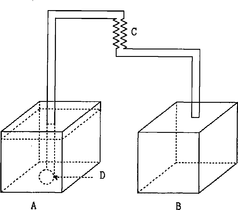
[0055] Example ( figure 1 )

[0056] Composition of water-based drag reducer: non-ionic surfactant fatty alcohol polyoxyethylene ether AEO-9 40ppm; methyl polysiloxane and nano-scale silicon dioxide as the main body, using a special emulsifier to emulsify the defoamer 8ppm , dodecyl dimethyl ammonium bromide fungicide 10ppm.

[0057] Such as figure 1 , as shown: the container A and container B of the device are two identical containers that can hold 15 liters of water, 30 cm high, with openings on the top, and are all placed on the ground; a submersible pump D is installed in the container A, and the power of the submersible pump D is 40 watts. The head is 160cm, the maximum flow rate is 2400 liters / hour; the outlet of submersible pump D is connected to plastic corrugated water pipe C, the diameter of water pipe C is 1.8cm, and the length is 500cm; 76cm, lay flat; the other end of the water pipe C is placed on top of the container B.

[0058] In application, the water and ...


PUM

PropertyMeasurementUnit
diameteraaaaaaaaaa

Abstract

The invention discloses a water-based drag reducer and application thereof. The water-based drag reducer comprises the following components in parts per million by weight: 30-200ppm of non-ionic surface active agent fatty alcohol-polyoxyethylene ether, 5-40ppm of defoaming agents or 5-40ppm of organopolysiloxane defoaming agents and 5-30ppm of dodecyl dimethyl ammonium bromide bactericides, wherein the 5-40ppm of defoaming agents or the 5-40ppm of organopolysiloxane defoaming agents are emulsified by using special emulsifiers and taking methyl polysiloxane and nanometer-grade silicon dioxide as main bodies. A method of mechanical kneading with multi-layer fine gauze filtering is adopted for mixed preparation so that the non-ionic surface active agent is dissolved in water in a foamy way; the adding temperature of the drag reducer is 5 DEG C-70 DEG C; when the drag reducer is used in a horizontal pipeline, the energy consumption of a water pump motor is reduced more than 20 percent at the same flow rate; and the increase rate of the water circulating flow rate of the horizontal pipeline using the drag reducer is 10-20 percent. The water-based drag reducer not only changes boundary conditions of the fluid interior and fluid and a pipe wall, but also changes the physical, chemical and mechanical properties of the fluid interior and boundary materials, thereby greatly reducing the resistance of a delivery pipeline and achieving the purpose of electricity saving of the water pump motor; and in addition, the water-based drag reducer and a validation method are scientific, reasonable and practical and open a new way for reducing the energy consumption of a circulating water system.

Description

technical field [0001] The invention relates to a drag reducer, especially a water-based drag reducer, which is suitable for application in circulating water systems. Background technique [0002] The chemical agent used to reduce fluid flow resistance is called drag reducer, which is divided into two types: one is oil-based (phase) drag reducer, which is used for crude oil and refined oil pipeline transportation; the other is water-based Resisting agent, used in circulating water system. [0003] There are already many oil-based (phase) drag reducer patents and products, such as: ①Patent No. 200610083720.4, a water-soluble drag reducer for oil wells; ②Patent No. 02806581.6, amorphous ultra-high molecular weight polyolefin used as a drag reducer Forming method; ③ Patent No. 03119743.4, a preparation method of poly-alpha-olefin drag reducer for pipeline oil products; ④ Patent No. 99808944.3, a manufacturing method of amorphous ultra-high molecular weight poly-alpha-olefin dr...

Claims


Application Information

Patent Timeline
Patent Type & Authority Applications(China)
IPC IPC(8): C02F1/68C02F1/50
Inventor 任西平任亮
Owner 任西平
Learn More