Energy-saving electric heating cooker

A technology of electric heating pan and heating device, which is applied to special materials for cooking utensils, cooking utensils, household utensils, etc. It can solve the problems of long single cooking time, potential safety hazards, and easy energy dissipation of hot air, so as to increase the effective The area of ​​radiation and absorption, the effect of enhancing the effect of directional radiation heating, and enhancing the effect of infrared heating

Inactive Publication Date: 2010-06-23
张华文
View PDF0 Cites 3 Cited by
  • Summary
  • Abstract
  • Description
  • Claims
  • Application Information

AI Technical Summary

Problems solved by technology

The direct contact between them includes the contact at the bottom and the contact at the side. This method is easy to burst due to the uneven heating of the inner tank and the difference in thermal expansion between the inner tank and the heating device, which will bring trouble and trouble to the user. There are security risks
The way of not contacting and leaving gaps between them is mainly air convection heat transfer and radiation heat transfer. The heating device through air convection first heats the air and then transfers the heat to the inner tank through the hot air. This indirect heat transfer method speed Slower and hot air is easy to disperse, resulting in energy waste; and the infrared normal total emissivity of the surface of the aluminum plate commonly used in the radiation mode is very low, generally not more than 0.3, and the aluminum plate with a highly polished surface is as low as 0.03 , the infrared absorption rate of the surface of the liner is also low
Therefore, the current air convection heat transfer and radiation heat transfer methods that do not contact and leave gaps between them have the technical defects of low heat transfer efficiency, long cooking time, and waste of energy; and, because the heat of the heating device is difficult to Passing it out will also cause the temperature of the electric heating pot shell to be too high, which will cause hot hands and certain potential safety hazards.

Method used


Image

  • Energy-saving electric heating cooker
  • Energy-saving electric heating cooker
  • Energy-saving electric heating cooker

Examples


no. 1 example

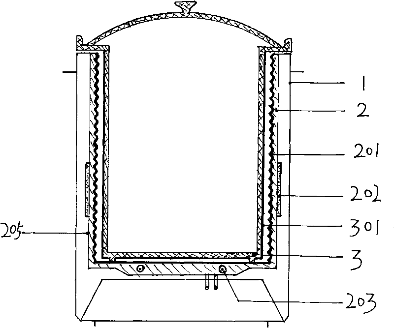
[0042] Such as figure 1 As shown, the energy-saving electric heating pot of the present embodiment, its side includes casing 1, barrel-shaped heating device 2, the liner 3 that non-metallic materials such as purple sand, pottery, ore, glass make successively from outside to inside, and it also Contains electrical controls. Wherein, the heating device 2 includes a barrel-shaped heat conductor such as aluminum, copper, iron, a tubular electric heating element 203 embedded in the bottom of the heat conductor, and a strip-shaped electric heating element 202 fixed on the outer side of the heat conductor; the inner surface of the heating device 2 is covered with Infrared radiating material layer 201, and its side part is threaded surface, and bottom is smooth surface; The outer surface of heating device 2 is infrared ray reflective surface 205, can keep smooth and clean surface, surface polishing, set zinc layer, titanium layer and other technologies. accomplish. The outer surface...

no. 2 example

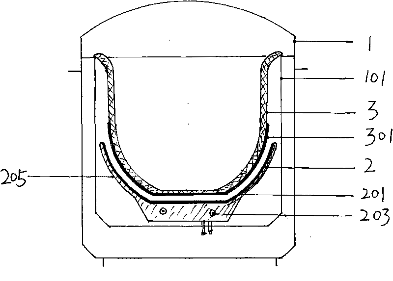
[0052] Such as figure 2 As shown, the energy-saving electric heating pot of the present embodiment includes a housing 1, a heat insulating layer 101 within the housing 1, and an inner shell made of non-metallic materials such as purple sand, pottery, ore, and glass within the heat insulating layer 101. Liner 3, a disk-shaped heating device 2 located at the bottom of the inner liner 3 and opposite to the outer surface of the lower part, and an electric control device. Wherein, the heating device 2 includes a tubular electric heating element 203 embedded in the bottom body, and the inner surface is covered with an infrared radiation material layer 201 , while the outer surface is an infrared reflective surface 205 . The bottom part of the outer surface of the inner container 3 opposite to the inner surface of the heating device 2 is covered with an infrared absorbing material layer 301 and is not in contact with the heating device 2 at all.

[0053] The outer surface of the he...

no. 3 example

[0056] Such as image 3 As shown, the energy-saving electric heating pot of the present embodiment includes a housing 1, a heat insulating layer 101 within the housing 1, and an inner shell made of non-metallic materials such as purple sand, pottery, ore, and glass within the heat insulating layer 101. Liner 3, the disk-shaped heating device 2 covering the lower part of the inner tank 3, the electric control device, and the suspension device 204 supporting the heating device 2. Wherein, the heating device 2 includes a tubular electric heating element 203 embedded in the bottom body, and a temperature-sensing probe 4 of an electric control device is arranged at the center of the bottom. The inner surface of the heating device 2 is covered with an infrared radiation material layer 201 , while the outer surface is an infrared reflective surface 205 . The lower outer surface of the liner 3 is covered with an infrared absorbing material layer 301 . The bottom of the inner surface...


PUM

PropertyMeasurementUnit
Thicknessaaaaaaaaaa

Abstract

The invention discloses an energy-saving electric heating cooker which adopts a nonmetal (purple sand, ceramic, ore, glass and the like) inner container. Infrared radiation material layers which are matched with each other are respectively arranged on the inner surface of a barrel / disc-shaped large-area heating device and on the outer surface of the inner container. The electric heating cooker increases the effective radiation and absorption area of infrared rays by the structural design of the surface and a covering layer, which not only greatly improves the heating function of the infrared radiation manner, but also can give attention to and exert the heating function of the conduction and convection manner. Therefore, the following beneficial effects are achieved: the heat efficiency is greatly increased, the heating speed is increased, the temperature of a shell is low, energy is saved, the heating area of the inner container is increased, the heating is uniform, the bursting is not easy, and the using is safe.

Description

technical field [0001] The invention relates to a cooking device heated by electric energy, in particular to an electric heating pot with fast, uniform, safe and energy-saving heating of non-metal inner containers such as purple sand, pottery, ore and glass. Background technique [0002] Because purple sand, ceramics and other non-metallic inner pot electric heating pots will not produce too many metal ions such as aluminum and will not fall off the non-stick coating and cause harm to human health, on the contrary, some materials can dissolve a variety of trace elements that are beneficial to the human body , and can make water weakly alkaline that is more beneficial to human health, make food taste better, and have the advantages of returning to natural flavors, etc. It has gradually been loved and used by more and more families. [0003] However, due to the physical characteristics of non-metallic materials such as purple sand and ceramics, such as low thermal conductivity...

Claims


Application Information

Patent Timeline
IPC IPC(8): A47J27/00A47J36/02
Inventor 张华文
Owner 张华文
Why Eureka
Try Eureka