
Optical fiber fusion splicer

An optical fiber fusion splicer and optical fiber connection technology, which is applied in the direction of optics, light guides, optical components, etc., can solve the problems of a lot of time required for work, increased manufacturing costs of fusion splicers, foreign matter on the screen, etc., to prevent external damage and/or damage , Reduce manufacturing costs, reduce the effect of time

Inactive Publication Date: 2010-06-16
ILSIN PRECISION CO LTD (KR)
View PDF1 Cites 28 Cited by
  • Summary
  • Abstract
  • Description
  • Claims
  • Application Information

AI Technical Summary

Problems solved by technology

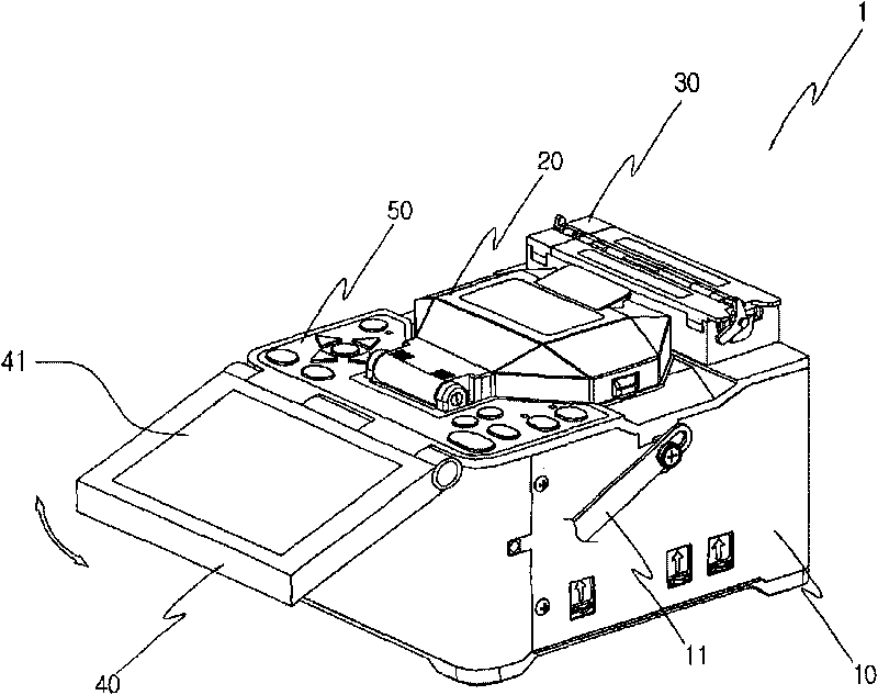
[0010] In the conventional fusion splicer (1) with the above-mentioned structure, since the monitor (40) is exposed outside the main body (10), it is easy to be damaged due to external force and the screen (41) is damaged by foreign objects during movement and / or storage. possibility of soiling
[0011] In addition, the conventional welding machine welds one sleeve in one heating shell, so it takes a lot of time to work.
In the case of U.S. Patent US20060280417A1, since two heating part casings are used, there is a problem that the occupied space is large and the manufacturing cost of the welding machine is increased.
In the actual connection, it takes 7 seconds to strip, wash, and cut the optical fiber, and 10 seconds to connect. However, it takes about 45 to 60 seconds to weld the sleeve, so the overall working time becomes longer due to insufficient heating of the casing.

Method used


Image

  • Optical fiber fusion splicer
  • Optical fiber fusion splicer
  • Optical fiber fusion splicer

Examples


Embodiment

[0042] Hereinafter, an optical fiber fusion splicer according to a preferred embodiment of the present invention will be described in detail with reference to the accompanying drawings.

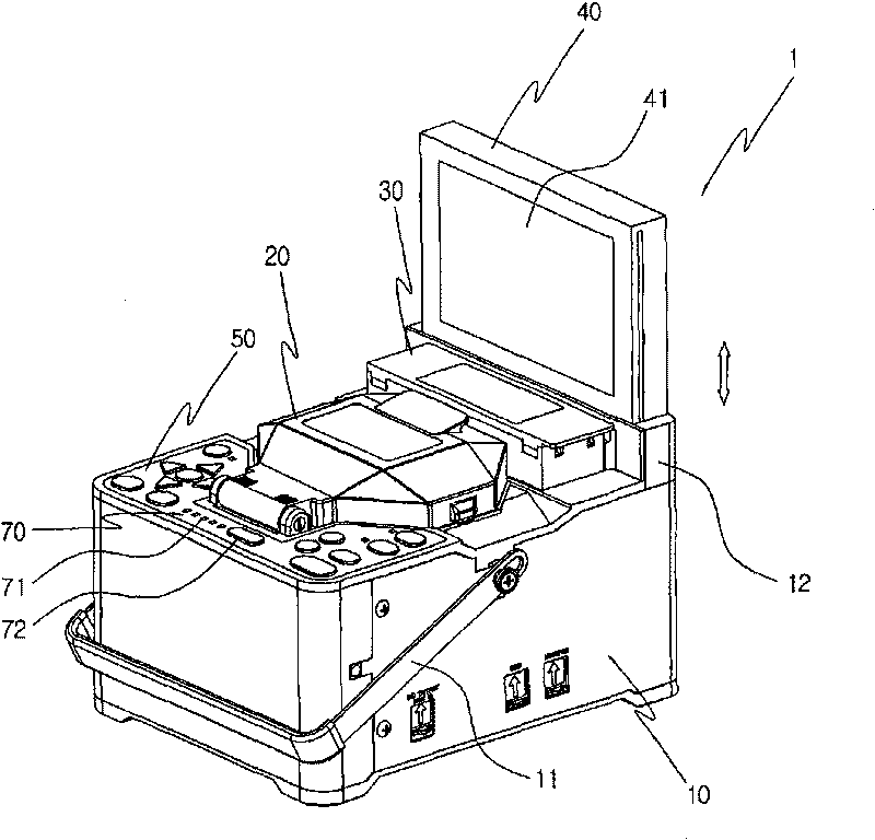
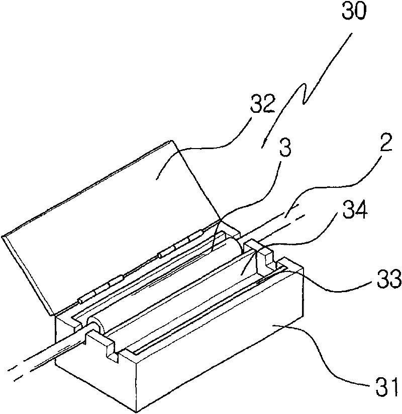
[0043] Such as figure 2 As shown, the fusion splicer (1) according to this embodiment includes a main body (10), a connecting part (20), a heating part (30), a monitor (40), an operating part (50), a fixing part (60) and a battery A remaining power display unit (70).

[0044] The main body (10) is used to install other components, and a handle (11) is provided at a predetermined position on the left side for easy movement of the connecting machine (1).

[0045] The connecting part (20) is used to connect the ends of two optical fibers, and is arranged on the upper surface of the main body (10).

[0046] The connection part (20), although not shown, is composed of a fixed cover for fixing the optical fiber, an electrode rod for fusing the optical fiber, an objective lens, an illuminating la...


PUM


Abstract

An optical fiber fusion splicer (1) includes a body (10); a joining part (20) disposed on the top portion of the body (10) to join ends of two optical fibers (2); a heating part (30) disposed on the top portion of the body to fuse a sleeve pipe (3) to the optical fibers, which are joined to each other; a monitor (40) disposed on the top portion of the body to monitor the connection state of the optical fibers; an operating part (50) disposed in the body to operate the joining part, the heating part (30) and the monitor (40); and a fixing part (60) detachably disposed on the top surface of the body so as to be positioned on one portion of the joining part. The sleeve pipe (3), which will be fused to the optical fibers (2), is fitted on the fixing part (60).

Description

technical field [0001] The present invention relates to an optical fiber fusion splicer, and more particularly, to an optical fiber fusion splicer capable of reducing the time required to connect optical fibers and the manufacturing cost of a heating unit while protecting a monitor for monitoring the connection state of optical fibers from the outside. Background technique [0002] The fusion splicer is a device for connecting two optical fibers, and it is equipped with a fusion splicing method using pigtails and a mechanical splicing method for emergency recovery and testing. figure 1 An example of such a fusion splicer is shown. [0003] Such as figure 1 As shown, the conventional optical fiber fusion splicer (1) is composed of a main body (10), a connecting part (20), a heating part (30), a monitor (40) and an operating part (50). [0004] The main body (10) is used to install other components, and a handle (11) is provided at a predetermined position on the left side i...

Claims


Application Information

Patent Timeline
Patent Type & Authority Applications(China)
IPC IPC(8): G02B6/255
CPCG02B6/2553G02B6/255
Inventor 宋在燮全相彻徐英培
Owner ILSIN PRECISION CO LTD (KR)
Learn More