
Mini inflating pump

A kind of pump and mini technology, applied in the field of pump to achieve the effect of reducing the volume

Inactive Publication Date: 2010-06-16
吴树木
View PDF1 Cites 6 Cited by
  • Summary
  • Abstract
  • Description
  • Claims
  • Application Information

AI Technical Summary

Problems solved by technology

[0006] The technical problem to be solved by the mini pump of the present invention is that it overcomes the shortcomings of the prior art, and feels the importance of the mini pump for bicycle riders. Its advantages of being light, small and easy to carry are beyond the reach of other pumps. How to make the operation of the mini pump more convenient and conform to the operating habits of each user is the purpose of the applicant's improvement. It is hoped that the present invention can eliminate or at least alleviate the problems encountered in the previous technology

Method used


Image

  • Mini inflating pump
  • Mini inflating pump
  • Mini inflating pump

Examples


Embodiment Construction

[0023] The above and other technical features and advantages of the present invention will be described in more detail below in conjunction with the accompanying drawings.

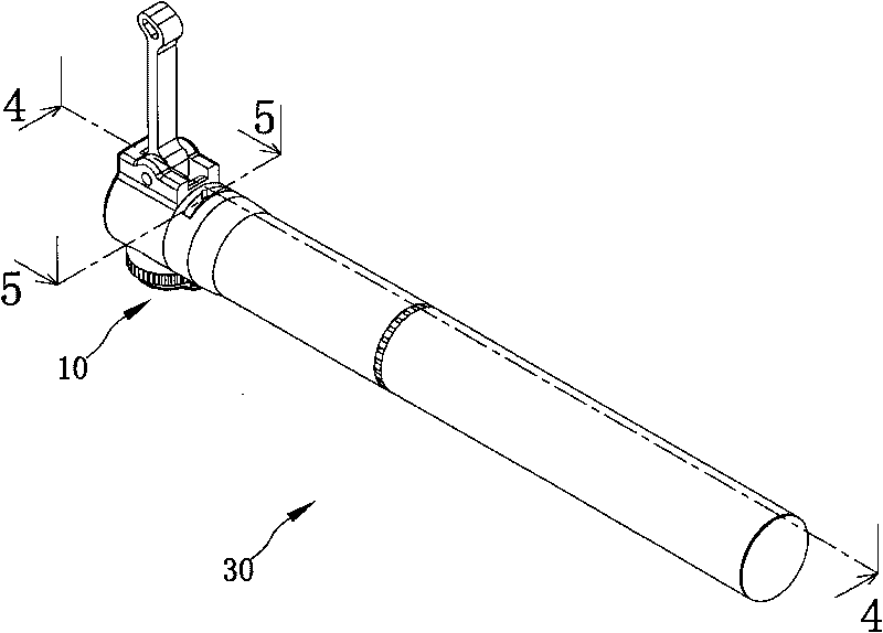
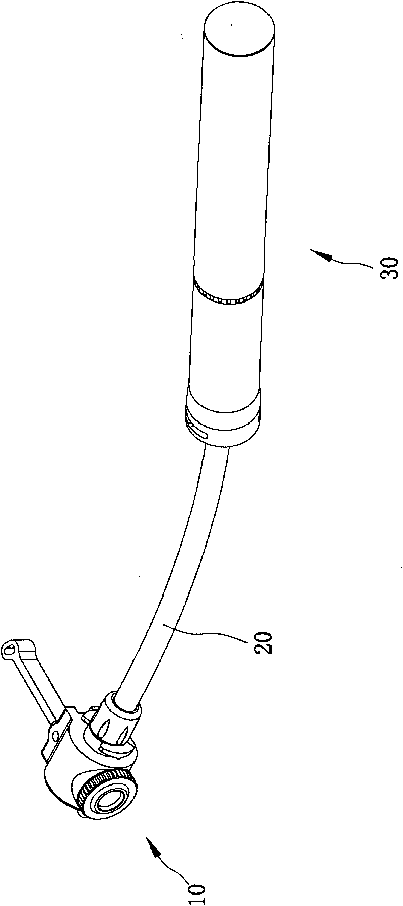
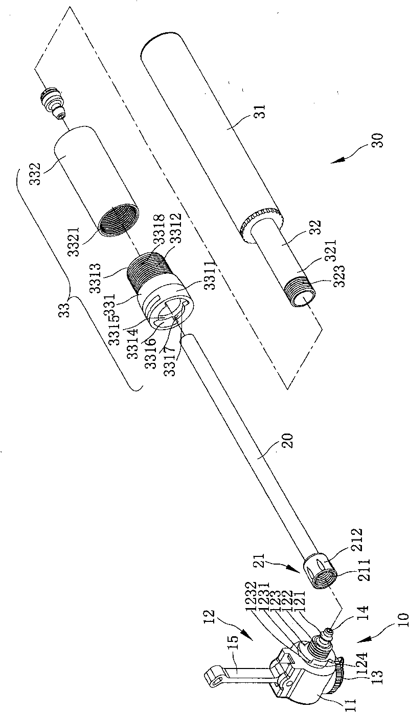
[0024] refer to figure 1 and figure 2 , is a three-dimensional appearance view of the mini pump in the first position and the second position of the present invention. The mini inflator of the present invention includes a head 10 , a hose 20 and an inflator 30 . The head 10 is combined with the hose 20, the inflator 30 is socketed on the hose 20, and the inflator 30 itself produces an inflating effect so that the gas enters the head 10 from the hose 20, Rotate the head 10 to further change the relative position of the head 10 and the inflator 30, so as to switch between the first position and the second position. When the head 10 is in the first position (such as figure 1 As shown), the head 10 is limited and fixedly combined with the inflator 30, when the head 10 is in the second position, the head 10...


PUM


Abstract

The invention relates to a mini inflating pump. The mini inflating pump comprises a head, a hose and an air inflating cylinder, wherein the head comprises a combination end, an air nozzle end and air passage, the air passage is communicated with the combination end and the air nozzle end, the head can rotate between a first position and a second position, one end of the hose is combined with the combination end of the head, the hose is optionally collected in the air inflating cylinder or exposed outside the air inflating cylinder, the air inflating cylinder is sheathed with the hose, and theair inflating cylinder generates the air inflating effect per se to introduce the air into the air passage of the head through the hose; when the head is at the first position, the head is limited inthe air inflating cylinder and the hose is collected in the air inflating cylinder; and when the head is at the second position, the head is optionally far away from the air inflating cylinder and the hose is properly exposed outside the air inflating cylinder.

Description

technical field [0001] The invention relates to an air pump, in particular to a mini air pump whose head and body can be relatively fixed and stretched, and which is suitable for different usage habits and occasions. Background technique [0002] With the popularization of bicycle sports, the portable air pump is more and more popular among cyclists. However, the mini air pump has the disadvantage of inconvenient filling due to its small size. [0003] Referring to the U.S. Patent No. 2007 / 0148023 "PUMP", it includes a handle and a handle body. One end of the handle body is connected with a head, and a handle rod is arranged inside the handle body. The rod achieves the effect of filling air in the handle body. [0004] The existing mini pump is also the design of the applicant, which meets the requirements of lightness and smallness, but the design of fixing the head and the handle body together, for users who use large pumps for a long time, the air nozzle on the head cann...

Claims


Application Information

Patent Timeline
Patent Type & Authority Applications(China)
IPC IPC(8): F04B33/00
Inventor 吴树木
Owner 吴树木
Learn More