


Quick Research
Generate reliable direction feasibility study reports for your R&D in just a few steps.

Technical Q&A
Discover and master advanced knowledge NOW. Basics, ideas, possibilities, all at once.

Find Solutions
As an expert in R&D theories, this can generate solutions to your technical problems instantly.

Evaluate Feasibility
Analyze your overall solution with one click, know your potential R&D risks in advance.

Monitor Landscape
Get weekly tech updates, stay abreast of the latest tech innovations and key insights.
Two-sided diaphragm filter plate heating and compression molding device and molding method thereof
A diaphragm filter plate and heating mold technology, applied in the field of diaphragm filter plate manufacturing, can solve problems such as easy bending deformation, uneven force on the filter plate core, and influence on the sealing degree of the diaphragm and filter plate, and achieve convenient thickness and reliable sealing Effect
- Summary
- Abstract
- Description
- Claims
- Application Information
AI Technical Summary
Problems solved by technology
Method used
Image

Examples
Embodiment 1
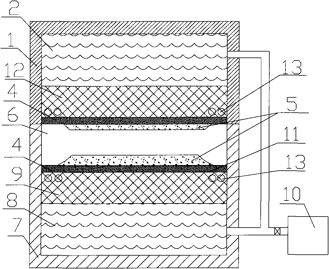
[0009] Embodiment 1: with reference to attached figure 1 . Double-sided diaphragm filter plate heating molding device, which includes an upper mold and a lower mold, the upper mold is an oil cylinder type upper mold 1 and the cavity 4 of the oil cylinder type upper mold 1 is a diaphragm forming cavity, and the forming surface 3 of the diaphragm forming cavity It is the oil cylinder piston 12 surface and the oil cylinder piston 12 is located in the upper mold oil chamber 2, and the diaphragm forming cavity molding surface 3 is provided with an electric heating tube 13 and the electric heating tube 13 is connected to the output end of the temperature controller through a wire; the lower mold It is an oil cylinder type lower mold 7 and the mold cavity of the oil cylinder type upper mold 7 is a filter plate 6 and a diaphragm forming cavity, the filter plate 6 is located in the mold cavity of the oil cylinder type lower die 7, and the forming surface 11 of the diaphragm forming cav...
Embodiment 2
[0010] Example 2: Double-sided diaphragm filter plate heating molding device and forming method, the filter plate 6 is embedded in the grooves on both sides of the degradable mold core 5, the plastic ball after plastic is placed on the surface of the lower mold of the oil cylinder, and the One side of the filter plate 6 of the drop-touch mold core 5 is placed in the lower mold of the oil cylinder and is in contact with the plasticized plastic mass, and then the plastic mass is placed on the other side of the filter plate 6. The upper mold 1 of the formula moves down, and the plastic balls located on both sides of the filter plate 6 are pressed on the two sides of the filter plate 6, and the double-sided diaphragm filter plate is formed after cooling. The degradable mold core 5 is paper or hydrolyzed material or hydrolyzed release agent. The pressures bear between the piston 12 and the piston 9 are equal.
PUM
 Abstract
Description
Claims
Application Information
 - R&D Engineer
- R&D Manager
- IP Professional
- Industry Leading Data Capabilities
- Powerful AI technology
- Patent DNA Extraction
Browse by: Latest US Patents, China's latest patents, Technical Efficacy Thesaurus, Application Domain, Technology Topic, Popular Technical Reports.
© 2024 PatSnap. All rights reserved.Legal|Privacy policy|Modern Slavery Act Transparency Statement|Sitemap|About US| Contact US: help@patsnap.com