Central shaft of continuously variable transmission of snowmobile

A technology of continuously variable transmission and central shaft, applied in the direction of shafts, shafts and bearings, portable lifting devices, etc., can solve problems affecting the working performance of the engine and continuously variable transmission, poor coaxiality of the central shaft, and unstable power transmission, etc., to achieve weakening Small, small pitch, smooth running effect

Inactive Publication Date: 2010-06-09
重庆永发科技有限公司
View PDF0 Cites 1 Cited by
  • Summary
  • Abstract
  • Description
  • Claims
  • Application Information

AI Technical Summary

Problems solved by technology

The current central shaft is a hollow shaft with an axis through hole, and a fixed plate is fixed at one end of the central shaft. The central shaft is provided with an engine output shaft mounting hole along its axis. The engine output shaft mounting hole is a straight hole for insertion. The shaft end is a cylindrical engine output shaft. The engine output shaft is inserted from the fixed plate end of the central shaft and connected with the central shaft through a key. Since there is a gap between the output shaft mounting hole of the central shaft and the output shaft, this traditional The key connection method, the center shaft and the engine output shaft are not concentric and the coaxiality is poor, resulting in unstable power transmission, making the continuously variable transmission with a counterweight mechanism unbalanced and vibrating during operation, affecting the working performance of the engine and the continuously variable transmission. Especially for snowmobile engines with large output power, heavy load, high speed and long-term operation, the resulting imbalance and vibration are more serious.

Method used


Image

  • Central shaft of continuously variable transmission of snowmobile
  • Central shaft of continuously variable transmission of snowmobile

Examples


Embodiment Construction

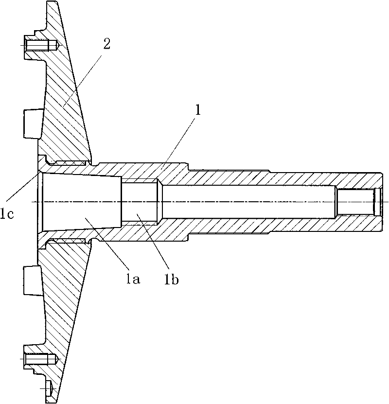
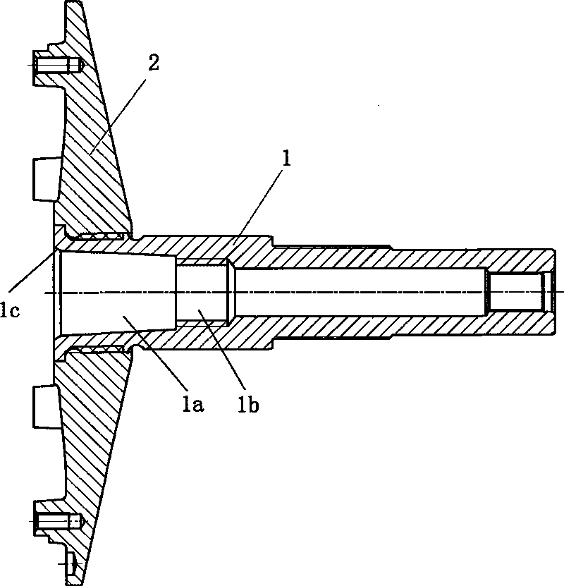
[0010] Below in conjunction with accompanying drawing and embodiment the present invention will be further described:

[0011] Such as figure 1 As shown, the present invention is a central shaft of a continuously variable transmission for a snowmobile. A fixed plate 2 is fixed at one end of the central shaft 1. The central shaft 1 is a hollow shaft provided with an axis through hole, and an engine output shaft is provided along its axis. Mounting hole, the mounting hole of the engine output shaft is composed of a taper hole 1a and a threaded hole 1b that are connected, the length of the taper hole 1a is about twice the length of the threaded hole 1b, and the large end of the taper hole 1a is fitted with a fixed shaft 1. The end faces of the disc ends are connected. For the convenience of assembly, a chamfer 1c is provided at the large end of the taper hole 1a. The thread direction of the threaded hole 1b is opposite to that of the central axis 1, and the thread fit will not lo...


PUM


Abstract

The invention discloses a central shaft of a continuously variable transmission of a snowmobile. A fixed disc (2) is fixed on one end of the central shaft (1); the central shaft (1) is a hollow shaft which is provided with an axial through hole; and an engine output shaft mounting hole is arranged along the axial line of the central shaft. The central shaft of the continuously variable transmission of the snowmobile is characterized in that: the engine output shaft mounting hole is formed by a taper hole (1a) and a screwed hole (1b) which are jointed; the large end of the taper hole (1a) is connected with the end surface of the end, which is provided with the fixed disc, of the central shaft (1); and the screwed hole (1b) is a fine-thread screwed hole. The central shaft of the continuously variable transmission of the snowmobile can ensure the concentricity and balance of the engine output shaft and a driving wheel of the continuously variable transmission and reduce the vibration during the running so as to effectively ensure the working performances of the engine and the continuously variable transmission of the snowmobile.

Description

technical field [0001] The invention relates to a continuously variable transmission mechanism, and more specifically relates to a central shaft of a continuously variable transmission of a snowmobile. Background technique [0002] The central shaft of the continuously variable transmission is the support for installing the main parts of the driving wheel, and it is also the power input part that transmits the engine power to the driving wheel. The output shaft of the engine is connected with the central shaft, and the power is transmitted from the output shaft of the engine. The current central shaft is a hollow shaft with an axis through hole, and a fixed plate is fixed at one end of the central shaft. The central shaft is provided with an engine output shaft mounting hole along its axis. The engine output shaft mounting hole is a straight hole for insertion. The shaft end is a cylindrical engine output shaft. The engine output shaft is inserted from the fixed plate end of...

Claims


Application Information

Patent Timeline
Patent Type & Authority Applications(China)
IPC IPC(8): F16H55/49F16C3/02
Inventor 蒋国峰
Owner 重庆永发科技有限公司
Why Eureka
Try Eureka