
Automatic lubrication system of rotating shuttle assembly of embroidery machine

An automatic lubrication and embroidery machine technology, which is applied to embroidery machines, embroidery machine mechanisms, textiles and papermaking, etc. It can solve the problems of not being able to refuel, oil stains on embroidery, not being able to refuel the hook shaft and the hook sleeve, etc., to achieve Improve work efficiency, increase rotation speed, and improve operation efficiency

Active Publication Date: 2010-06-02
ZHUJI CHUANGJIA ELECTRONICS EQUIP
View PDF1 Cites 9 Cited by
  • Summary
  • Abstract
  • Description
  • Claims
  • Application Information

AI Technical Summary

Problems solved by technology

[0002] The rotary hook assembly of the existing embroidery machine includes a rotary hook, a rotary hook shaft sleeve, and a rotary hook shaft. The shuttle shaft sleeve is easy to wear and needs to be lubricated frequently, and the commonly used lubrication method is to manually or automatically drop the lubricating oil into the oil groove set on the hook and the needle plate, because the oil in the oil groove flows to the lubricating parts through multiple oil seepages. The oil seepage hole is small and easy to be blocked by dust, so it is difficult to achieve a good lubricating effect; in addition, because the oil is directly added to the rotary hook, the amount of oil injected cannot be controlled, and the oil in the rotary hook is often thrown onto the embroidery. Oil stains will be produced on the embroidery, and the quality of the embroidery will be unqualified. Therefore, in actual use, there is little or no oil on the rotary hook, resulting in easy wear and tear on the rotary hook and the rotary hook shaft
In order to reduce the wear of the rotary hook and the rotary hook shaft, improve the lubricating effect, and prevent the lubricating oil from being thrown onto the embroidery, a Chinese utility model patent with the patent number "200820062628.6" and the name "automatic refueling mechanism for the rotary hook of an embroidery machine" has disclosed a An automatic refueling mechanism for a rotary hook, which is provided with a shaft center through hole on the axis of the rotary hook shaft, one end communicates with the oil control mechanism, and the other end communicates with the rotary hook. The automatic refueling mechanism for the rotary hook with this structure can only Refueling of the rotary hook, neither the rotary hook shaft and the rotary hook sleeve, nor the scissors and other parts around the rotary hook that need to be lubricated. Lubrication problems of adjacent components

Method used


Image

  • Automatic lubrication system of rotating shuttle assembly of embroidery machine
  • Automatic lubrication system of rotating shuttle assembly of embroidery machine
  • Automatic lubrication system of rotating shuttle assembly of embroidery machine

Examples


Embodiment Construction

[0022] Below in conjunction with accompanying drawing and embodiment the present invention will be further described:

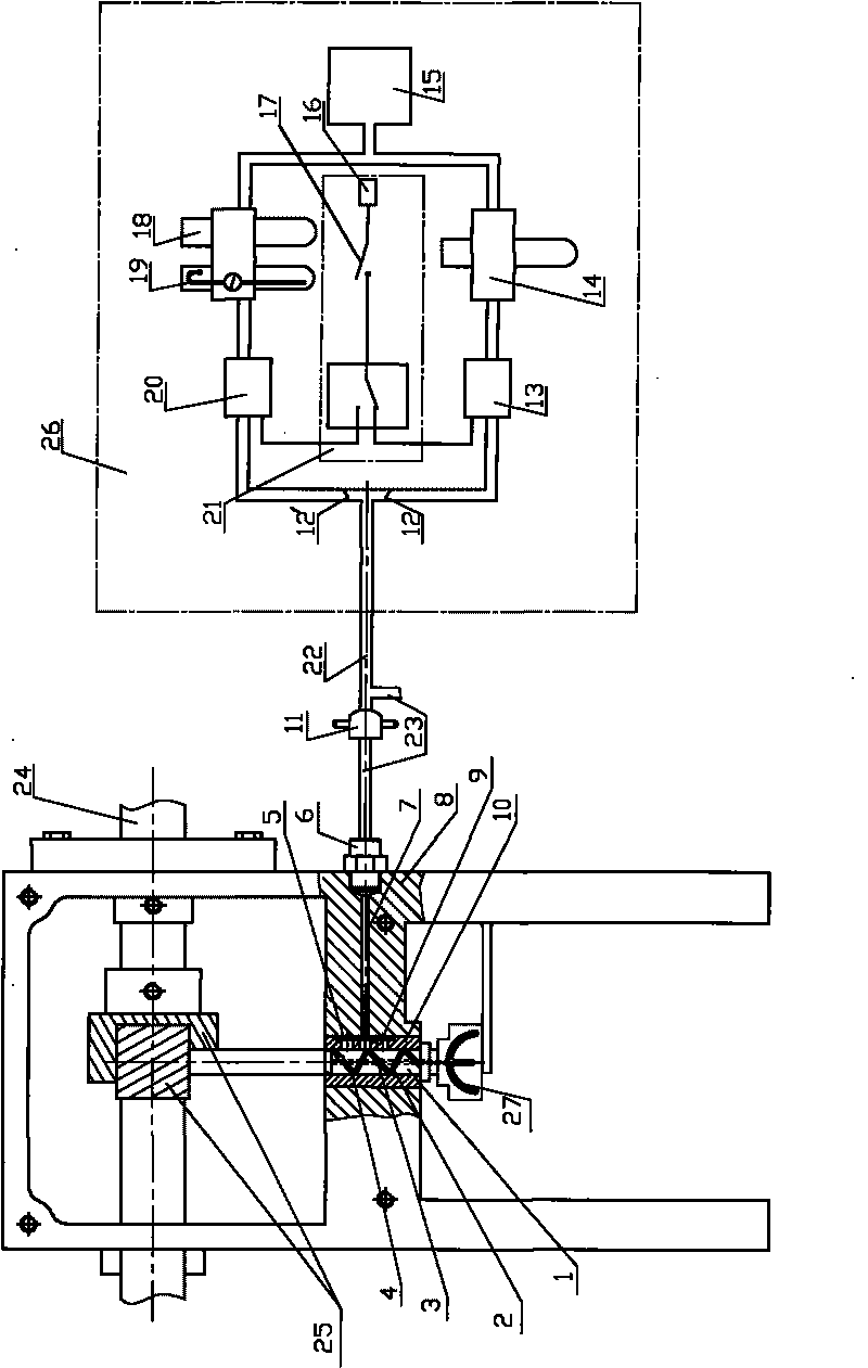
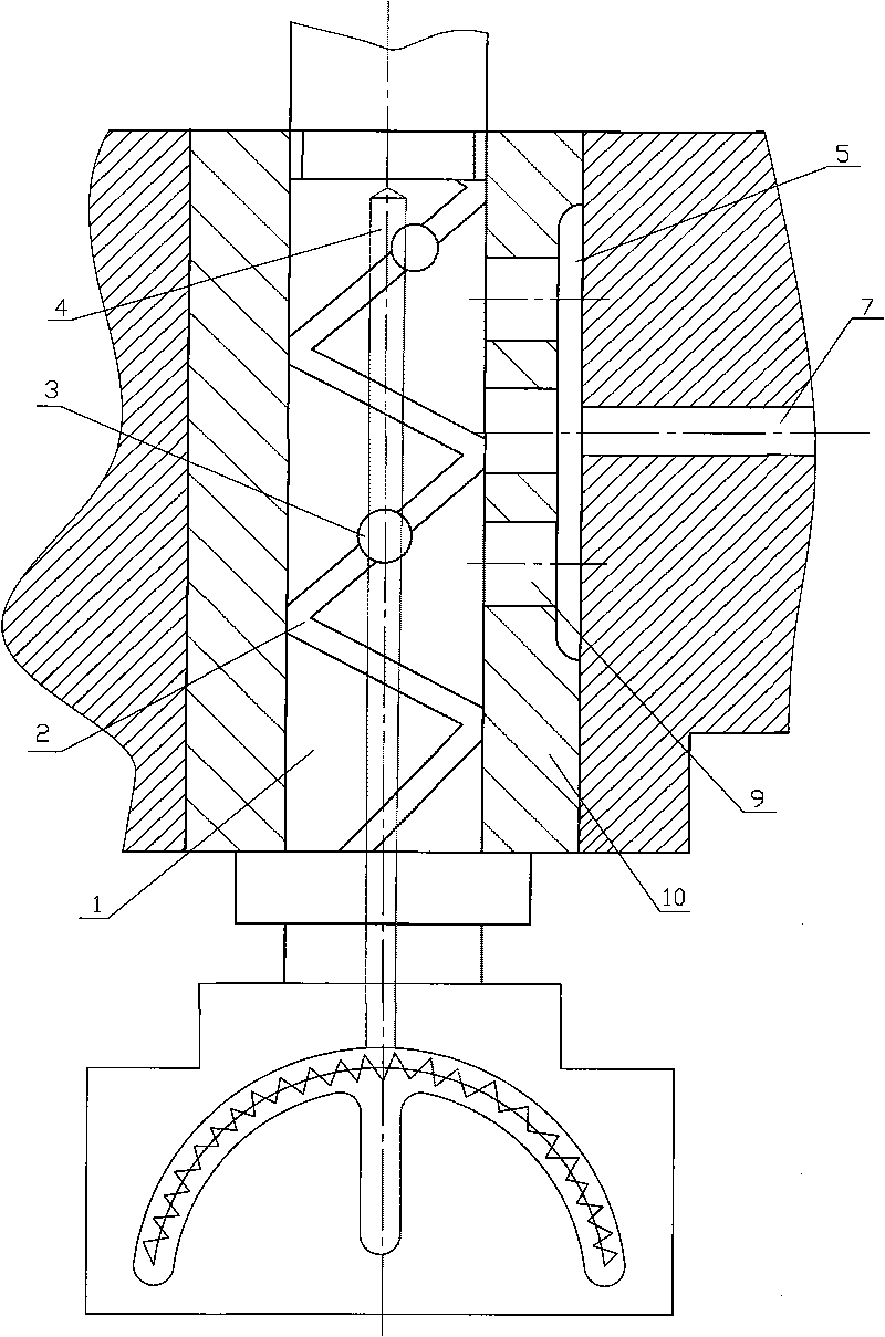
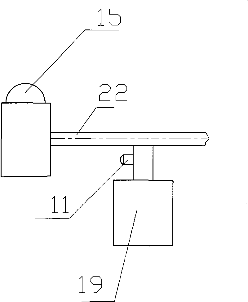
[0023] Such as figure 1 with 2 As shown, the automatic lubrication system of the rotary hook assembly of the embroidery machine of the present invention includes a rotary hook assembly oil supply device and a rotary hook assembly. The rotary hook assembly includes a rotary hook 27, a rotary hook shaft 1, a rotary hook sleeve 10, One end is fixedly connected with the rotary hook 27, and the other end is connected with the main transmission shaft 24 through the meshing gear. The rotary hook sleeve 10 is fixedly arranged on the rotary hook box 8 through the top screw, and the rotary hook shaft 1 rotates with the rotary hook sleeve 10. Fitted connection, the hook shaft 1 is provided with an axial blind hole 4, the through-hole end of the blind hole 4 communicates with the inner cavity of the hook 27, and is outside the matching part of the hook shaft 1 and the h...


PUM


Abstract

The invention relates to an automatic lubrication system of a rotating shuttle assembly of an embroidery machine, in particular to a lubrication system of a rotating shuttle assembly, which comprises a rotating shuttle, a rotating shuttle shaft and a rotating shuttle shaft sleeve, wherein a blind hole which is coaxial to the rotating shuttle shaft is arranged in the rotating shuttle shaft, the end of a through hole of the blind hole is communicated with an inner cavity of the rotating shuttle, and an oil through hole which is communicated with the blind hole is arranged on the surface of the rotating shuttle shaft. The invention can not only continuously charge oil into the rotating shuttle, the rotating shuttle shaft and the shaft sleeve thereof, but also can cool and clean the components.

Description

technical field [0001] The invention relates to an automatic lubricating system for an embroidery machine rotary hook assembly, in particular to an automatic lubrication system for an embroidery machine rotary hook assembly composed of a rotary hook, a rotary hook shaft and a rotary hook shaft sleeve. Background technique [0002] The rotary hook assembly of the existing embroidery machine includes a rotary hook, a rotary hook shaft sleeve, and a rotary hook shaft. The shuttle shaft sleeve is easy to wear and needs to be lubricated frequently, and the commonly used lubrication method is to manually or automatically drop the lubricating oil into the oil groove set on the hook and the needle plate, because the oil in the oil groove flows to the lubricating parts through multiple oil seepages. The oil seepage hole is small and easy to be blocked by dust, so it is difficult to achieve a good lubricating effect; in addition, because the oil is directly added to the rotary hook, t...

Claims


Application Information

Patent Timeline
IPC IPC(8): D05C13/04D05C11/00
Inventor 陈韦东
Owner ZHUJI CHUANGJIA ELECTRONICS EQUIP
Learn More