Over-long threaded heat pipe of sucker rod

A sucker rod, heat pipe technology, applied in drill pipe, drill pipe, casing and other directions, to achieve the effect of convenient operation, increase heat transfer surface area, and prevent wax precipitation

Inactive Publication Date: 2010-05-26
DAQING GASOLINEEUM INST
View PDF0 Cites 1 Cited by
  • Summary
  • Abstract
  • Description
  • Claims
  • Application Information

AI Technical Summary

Problems solved by technology

[0005] The technical problem to be solved by the present invention is to overcome the difficulty in effectively producing good two-phase boiling and condensation heat transfer on the inside of the heat pipe with a smooth wall surface in the background technology, which causes heat transfer obstacles inside the heat pipe and the difficulty in effectively forming a good single convection flow on the outside of the heat pipe. In order to solve the problem of heat exchange, an ultra-long sucker rod threaded heat pipe is provided. Because the inner and outer surfaces of the pipe wall are threaded, the heat exchange and heat transfer area is increased, and the heat transfer barrier inside the heat pipe is reduced and strengthened. The single convective heat exchange on the outside of the heat pipe ensures the efficient heat transfer of the sucker rod heat pipe, inhibits the wax precipitation of crude oil, reduces the viscosity of crude oil, and ensures the normal operation of the sucker rod

Method used


Image

  • Over-long threaded heat pipe of sucker rod
  • Over-long threaded heat pipe of sucker rod
  • Over-long threaded heat pipe of sucker rod

Examples


Embodiment Construction

[0024] The invention will be further described below in conjunction with accompanying drawing:

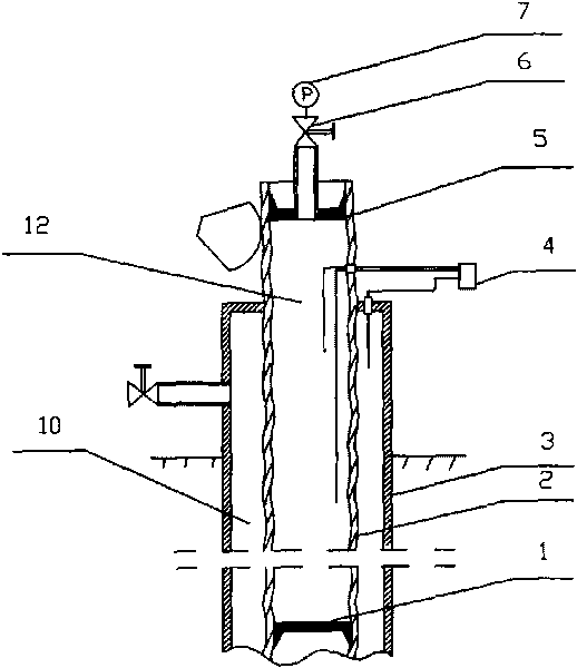
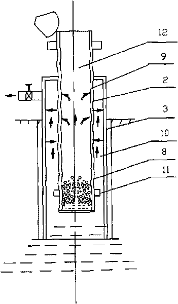
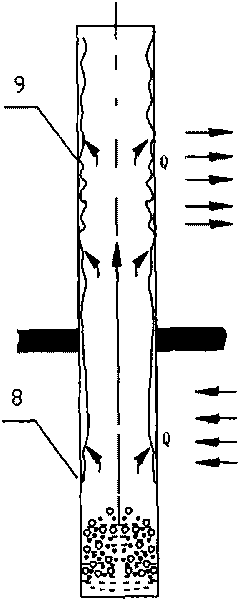
[0025] attached figure 1 to combine figure 2 As shown, the super-long sucker rod threaded heat pipe includes a sucker rod heat pipe 2 formed by sealingly connecting several sucker pipe sections. The inner cavity of the sucker rod heat pipe 2 forms a sealed cavity 12 filled with a working medium, and the sealed cavity The upper section of 12 is the heat pipe condensation section 9, the lower section of the sealed chamber 12 is the heat pipe evaporation section 8, the cavity body of the sealed chamber 12 is a threaded tubular shape, and the sealed chamber 12 is sealed by the upper plug cover 5 installed on the upper end of the sucker rod. The lower plug 1 at the bottom of the sucker rod and the sucker rod heat pipe 2 with the working medium between the upper and lower plugs are formed. The position of the lower plug 1 should be determined according to the temperature of the oil re...


PUM


Abstract

The invention relates to an over-long threaded heat pipe of a sucker rod, mainly solving the problems of heat transfer barrier of the inner part of the heat pipe and difficulty of effectively forming good single-phase flow heat transfer on the outer side of the heat pipe because the inner side of the heat pipe with a smooth wall surface in the prior art is difficult to effectively produce good two-phase boiling and condensation heat transfer. The heat pipe is characterized in that a cavity of a sealing cavity (12) is of a threaded pipe shape; the sealing cavity (12) comprises an upper blocking cover (5), a lower blocking cover (1) and the heat pipe of the sucker rod (2), wherein the upper blocking cover (5) is closely installed on the upper end of the sucker rod; the lower blocking cover (1) is closely installed in the lower part of the sucker rod; and the heat pipe of the sucker rod (2) is provided with working media between the upper blocking cover and the lower blocking cover. Because the inner surface and the outer surface of the pipe wall have threads which increase the area of heat transfer, the over-long threaded heat pipe of the sucker rod reduces the heat transfer barrier of the inner part of the heat pipe, strengthens the single-phase flow heat transfer on the outer side of the heat pipe, ensures the high-efficiency heat transfer of the heat pipe of the sucker rod, inhibits the wax precipitation of crude oil, reduces the viscosity of the crude oil, and ensures the normal operation of an oil sucking machine.

Description

Technical field: [0001] The utility model relates to a sucker rod heat pipe used in the field of oil production in an oil field, in particular to a super-long sucker rod threaded heat pipe. Background technique: [0002] In heavy oil wells, high-condensation oil wells and high-wax oil wells in oil fields, electric heating and other equipment are placed in the sucker rod to improve the fluidity of wellbore crude oil. The upper end of this type of sucker rod protrudes from the wellhead and is connected with the pumping unit, and the lower end is connected with the oil well pump. Relying on the reciprocating motion of the oil pump and the pumping unit, the crude oil is pumped up from the ground and discharged from the wellhead of the oil well. Generally, the length of the sucker rod varies with the depth of the oil layer, most of which are above 1000m. The outer diameter of the sucker rod is generally 36-51mm, and the wall thickness is 6-8mm. The sucker rods used in oil well...

Claims


Application Information

Patent Timeline
Patent Type & Authority Applications(China)
IPC IPC(8): E21B43/24E21B17/00
Inventor 王淑彦刘永建王常斌杜婉琳
Owner DAQING GASOLINEEUM INST
Why Eureka
Try Eureka