
Direct pyrolysis device

A thermal analysis and equipment technology, applied in the field of soil remediation, can solve the problems of soil loss of performance and function, high cost of incineration technology treatment, damage to soil physical and chemical properties, etc., to achieve reasonable design structure, high-efficiency processing capacity, and high energy consumption. Effect

Active Publication Date: 2010-05-26
BCEG ENVIRONMENTAL REMEDIATION CO LTD
View PDF0 Cites 47 Cited by
  • Summary
  • Abstract
  • Description
  • Claims
  • Application Information

AI Technical Summary

Problems solved by technology

Since the incineration temperature is as high as 1000-2000 ℃, it will directly destroy the physical and chemical properties of the soil, make the soil lose its original performance and function, and directly destroy the non-renewable resource of soil; and it is difficult to control the secondary process of the incineration process. generation of pollution
In short, incineration technology has high processing costs and is not friendly to the environment

Method used


Image

  • Direct pyrolysis device
  • Direct pyrolysis device
  • Direct pyrolysis device

Examples


Embodiment Construction

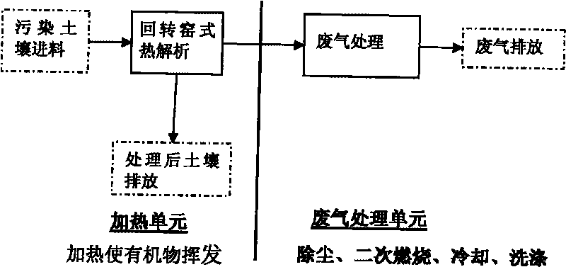
[0029] figure 1 As a structural block diagram of the present invention, the present invention provides a direct thermal desorption device, including a feeding part 1, an auxiliary part 2, a heating part, a dust removal part, a quenching part 6, a washing part 8 and a discharge part, wherein the heating part includes a primary heating Part 3 and secondary heating part 5, feeding part 1 and auxiliary part 2 are all connected with primary heating part 3; dust removal part includes primary dust removal part 4 and secondary dust removal part 7, and discharge part includes gas discharge device 9 and soil discharge device 10. The primary heating part 3 is sequentially connected with the primary dust removal part 4, the secondary heating part 5, the quenching part 6, the secondary dust removal part 7, the washing part 8 and the gas discharge device 9. In addition, the primary heating part 3 is also connected with the soil discharge device 10 connected. The feeding part, auxiliary pa...


PUM


Abstract

The invention relates to a direct pyrolysis device. In the direct pyrolysis device, a heating part comprises a primary heating part and a secondary heating part; both a feed part and an auxiliary part are connected with the primary heat part; a dedusting part comprises a primary dedusting part and a secondary dedusting part; an emission part comprises a gas emission device and a soil emission device; the primary heating part is orderly connected with the primary dedusting part, the secondary heating part, a quenching part, the secondary dedusting part, a washing part and the gas emission device; the primary heating part is also connected with the soil emission device; all the components are respectively connected with a monitoring part; the washing part is a washing tower; and the tail end of the washing tower is connected with the gas emission device. The invention has the advantages of high handling capacity, low energy consumption, low handling cost and the like, maintains the advantages of physico-chemical properties of soil and the like, and can effectively separate organic substances from contaminated soil and dispose the contaminated soil.

Description

technical field [0001] The invention belongs to the field of soil restoration, in particular to thermal analysis equipment, especially direct thermal analysis equipment. Background technique [0002] Thermal desorption technology is an important contaminated soil remediation technology, which can remediate the soil that has been polluted by organic matter, and can achieve a good remediation effect. It uses heating to heat the soil polluted by organic matter to above the boiling point of the organic matter, so that the organic matter adsorbed in the soil is volatilized into a gaseous state and then separated. Thermal desorption technology can effectively remove volatile organic compounds, such as aromatic hydrocarbons, etc., and can also effectively remove low-volatility and refractory organic pollutants such as PCBs, DDT, Dioxins, and chlorine-containing pesticides. Organic pollutants with different boiling points can be heated at one time to achieve the remediation target ...

Claims


Application Information

Patent Timeline
IPC IPC(8): B09C1/06B01D50/00B01D46/02B01D47/06
Inventor 翟立前商盈李书鹏李瓒王瑞娟谭勇壁
Owner BCEG ENVIRONMENTAL REMEDIATION CO LTD
Learn More