
Steam jet waste steam recycling device and steam jet waste steam recycling system

A circulating device and jet technology, which is applied in the field of residual steam recovery of steam systems, can solve the problems of difficult to achieve pressure and suction capacity, difficult to adapt to load changes, limited application scope, etc., to achieve process steam optimization, equipment The effect of expanding the load coverage and reducing the amount of bypass adjustment

Inactive Publication Date: 2010-05-12
CHONGQING GIENT ENERGY SAVING TECH
View PDF0 Cites 21 Cited by
  • Summary
  • Abstract
  • Description
  • Claims
  • Application Information

AI Technical Summary

Problems solved by technology

Because the critical section required by the diffuser cannot be formed, it becomes a Venturi tube, so it is difficult to achieve the pressure and suction capacity we need.
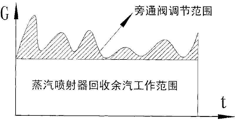
[0007] Through the above analysis, it can be seen that the operating range of the steam ejector (heat pump) is only allowed to work within a small range of change, and it is difficult to adapt to the situation of large load changes.
However, the load of a large number of steam systems that are being applied often fluctuates within a wide range, which limits the application range of the above-mentioned systems
Even with the addition of the best self-regulating equipment, it is difficult to resolve the above contradictions

Method used


Image

  • Steam jet waste steam recycling device and steam jet waste steam recycling system
  • Steam jet waste steam recycling device and steam jet waste steam recycling system
  • Steam jet waste steam recycling device and steam jet waste steam recycling system

Examples


Embodiment Construction

[0033] The concrete structure and working process of device and system proposed by the present invention are described in detail below:

[0034] 1. Steam recovery device with bypass:

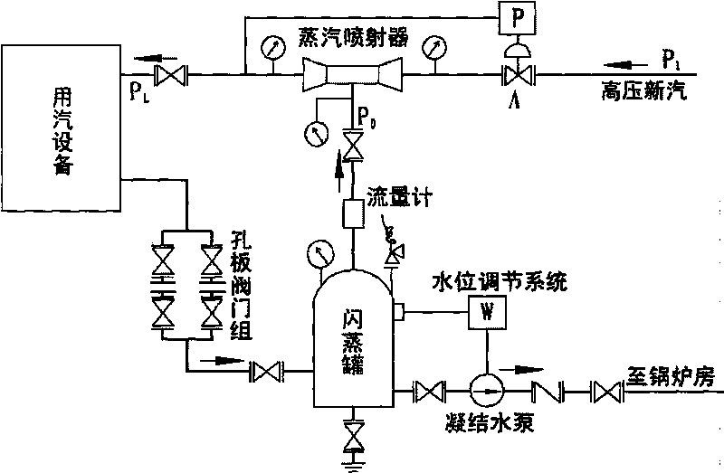
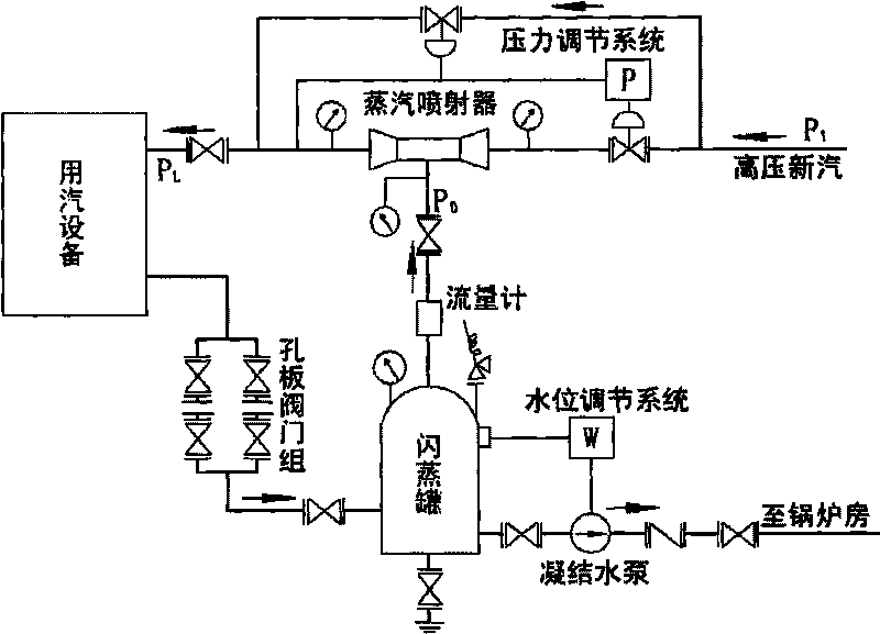
[0035] see figure 2 , the device includes a steam ejector, a process heat exchanger, an orifice valve group, a flash tank and a condensate pump connected sequentially through pipelines. The top of the flash tank connects the residual steam to the suction port of the steam ejector through the pipeline, and the steam inlet of the steam ejector is connected to the fresh steam from the heat source, and at the same time, the steam inlet end of the steam ejector is connected with a valve with a regulating valve. Bypass, the bypass is directly connected from the steam inlet end of the steam injector to its steam outlet end. The outlet pipe of the condensate pump is connected to the boiler room. The pipelines of the device are equipped with electric valves at the inlet of the steam injector, regulat...


PUM


Abstract

The invention discloses a steam jet waste steam recycling device. In the device, the steam inlet end of a steam ejector is connected with a bypass with an adjustment valve; and at least two steam ejectors are connected in parallel. Two or more steam jet waste steam recycling devices are connected in series to form a waste steam recycling system; the steam pressure parameter of one suite of device is higher than that of the other suite; high-pressure process steam generated by the device with the higher steam pressure parameter is divided into two paths for output, wherein one path is connected with each steam equipment needing to use the pressure, while the other path is connected with the steam inlet end of the other device with the lower steam pressure parameter to be used as the admitted steam of the other device. The device and the system disclosed by the invention can enable the steam jet waste steam recycling system to make the steam ejectors work stably under the condition of relatively larger load fluctuation, simultaneously achieve relatively better energy-saving effect, meet requirements on the process pressure PL and flow rate GL at any time and ensure the process steam equipment to rationally run with assured quality and quantity.

Description

technical field [0001] The invention belongs to the technical field of thermal engineering, and in particular relates to the residual steam recovery technology of a steam system. Background technique [0002] Various steam systems consume a lot of energy, and industrial and civil boilers alone consume about 500 million tons of raw coal each year, mainly to meet the use of steam systems. [0003] At present, more than 85% of steam systems use surface heat exchangers to meet the needs of industry and civil use. During the use of the steam surface heat exchanger, the steam and the working medium conduct heat transfer. The heat transfer steam is condensed on the heat release surface, and the condensed water passes through the steam trap, so that only the water flows out and the steam does not leak out. However, due to the quality and structural problems of the trap, it is still difficult to achieve the desired effect. The steam leakage of general steam traps can reach more tha...

Claims


Application Information

Patent Timeline
IPC IPC(8): F17D1/06F22D11/06
Inventor 赵志立彭俊李磊王健李亮邹鉴通
Owner CHONGQING GIENT ENERGY SAVING TECH
Learn More