Built-in dispersed heating type drying equipment

A drying equipment and heating technology, which is applied to layered products, devices for coating liquid on the surface, printing, etc., can solve the problems of limiting the scope of application, complicated and huge equipment, etc., to save energy required for heating and ensure Drying speed, the effect of promoting complete evaporation

Inactive Publication Date: 2010-05-12
简苏 +1
View PDF1 Cites 7 Cited by
  • Summary
  • Abstract
  • Description
  • Claims
  • Application Information

AI Technical Summary

Problems solved by technology

This utility model undoubtedly has obvious progress in improving drying performance, energy saving and safety, but the equipment is too complicated and bulky, and can only achieve two drying temperatures, which undoubtedly limits its application range

Method used


Image

  • Built-in dispersed heating type drying equipment
  • Built-in dispersed heating type drying equipment
  • Built-in dispersed heating type drying equipment

Examples


specific Embodiment 1

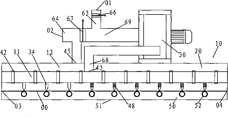
[0052] The drying equipment described in this embodiment is suitable for a coating machine.

[0053] refer to figure 1 , the present embodiment comprises oven 10, blower fan 30 and heater 48, and the air outlet of blower fan communicates with oven cavity; Described oven 10 comprises oven cover 20, base 50, is provided with between oven cover 20 and base 50 The transmission channel of the printed product; the oven cover 20 is provided with an air inlet chamber 11 and several nozzles 34; the nozzles 34 communicate with the air inlet chamber 11 or are arranged in the air inlet chamber 11, and the air outlets of the nozzles 34 are used for conveying The conveying channel of the printed matter forms a built-in decentralized heating mechanism; the air outlet of the fan 30 communicates with the air inlet 43 of the air inlet chamber 11 through the air inlet channel 68 .

[0054] This embodiment also includes a connecting air duct and an exhaust system. The oven 10 is provided with ...

specific Embodiment 2

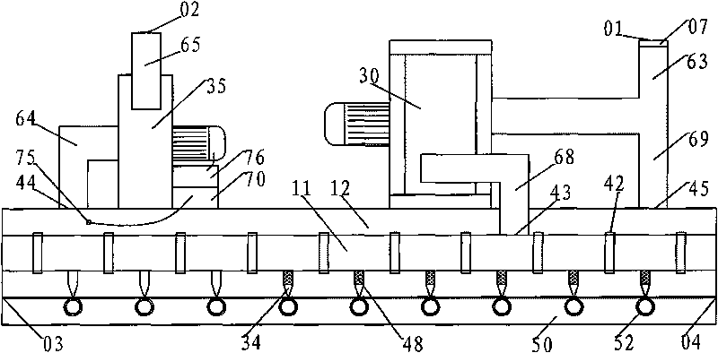
[0066] The drying equipment described in this embodiment is suitable for a coating machine. It is obtained by improving the shortcoming of specific embodiment 1 that the energy-saving effect is not significant.

[0067] refer to figure 2 , The drying equipment described in this embodiment is composed of an oven 10, a fan 30, an exhaust fan 35, a control drive device 70, a connecting air duct, and an exhaust system.

[0068] The oven 10 includes an oven cover 20, a base 50, and is provided with a printed product inlet 03 and a printed product outlet 04;

[0069] The oven cover 20 includes an air inlet chamber 11 , an air exhaust chamber 12 , ten nozzles 34 , and ten heaters 48 .

[0070] The air inlet cavity 11 is provided with an air inlet 43 , which communicates with the air outlet of the fan 30 through the air inlet channel 68 .

[0071] The heater 48 is installed in the air inlet chamber 11 , and the nozzle 34 communicates with the air inlet chamber and is installed on ...


PUM


Abstract

The invention relates to built-in dispersed heating type drying equipment, which comprises an oven (10), a fan (30) and a heater (48). An air outlet of the fan is communicated with an inner cavity of the oven; the oven (10) comprises an oven cover (20) and a base (50); and a transfer passage used for transferring printed products is arranged between the oven cover (20) and the base (50). The drying equipment is characterized in that 1) an air inlet cavity (11) and a plurality of nozzles (34) are arranged in the oven cover (20); the nozzles (34) are communicated with the air inlet cavity (11) or arranged in the air inlet cavity (11), and air outlets of the nozzles (34) face the transfer passage used for transferring the printed products so as to form a built-in dispersed heating type mechanism; and 2) the air outlet of the fan (30) is communicated with an air inlet (43) of the air inlet cavity (11) through an air inlet passage (68). The built-in dispersed heating type drying equipment is widely applied to processing equipment such as coating machines, compound machines, printing machines, roller coating wires, size machines and the like, and can also be used for drying continuous transferred articles.

Description

technical field [0001] The invention relates to a built-in dispersive heating drying equipment, which is suitable for drying continuously traveling thin strip-shaped objects (hereinafter referred to as printed products), and is widely used in coating machines, compound machines, printing machines, roll coating lines, gluing lines, etc. Machines and similar processing equipment can also be used to dry continuously conveyed items. It belongs to the technical field of drying equipment such as printing and coating. Background technique [0002] At present, the processing equipment for thin strip objects generally has the following characteristics: the printed product is a thin strip object that travels continuously, such as plastic film, thin metal plate, etc. Continuous processing in the process. The surface of the processed product or product substrate is first covered with one or more layers of substances, such as ink, paint, glue, etc., using the transfer device of the equ...

Claims


Application Information

Patent Timeline
Patent Type & Authority Applications(China)
IPC IPC(8): B05D3/02B41F23/04B32B38/16
Inventor 简甦
Owner 简苏
Why Eureka
Try Eureka