
Wave-soldering unit and mechanical gripper thereof

A technology of wave soldering and mechanical claws, applied in the direction of manipulators, welding equipment, auxiliary devices, etc., can solve problems such as workpiece deformation, uneven force applied to clamping points, and workpiece damage

Inactive Publication Date: 2010-05-05
深圳市诺斯达科技有限公司
View PDF0 Cites 19 Cited by
  • Summary
  • Abstract
  • Description
  • Claims
  • Application Information

AI Technical Summary

Problems solved by technology

Due to the manufacturing and / or assembly errors of the equipment, it is easy to cause uneven force at each clamping point, which can easily cause deformation of the workpiece, and even damage to the workpiece in serious cases

Method used


Image

  • Wave-soldering unit and mechanical gripper thereof
  • Wave-soldering unit and mechanical gripper thereof
  • Wave-soldering unit and mechanical gripper thereof

Examples


Embodiment Construction

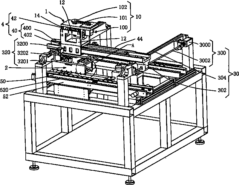
[0025] Such as figure 1 As shown, the present invention provides a mechanical claw of a wave soldering machine, including a lifting displacement device 1, a pair of claw bodies 2 driven up and down by the lifting displacement device 1, and a mechanism for driving the pair of claw bodies 2 to realize the opening and closing action. Zhanghe system.

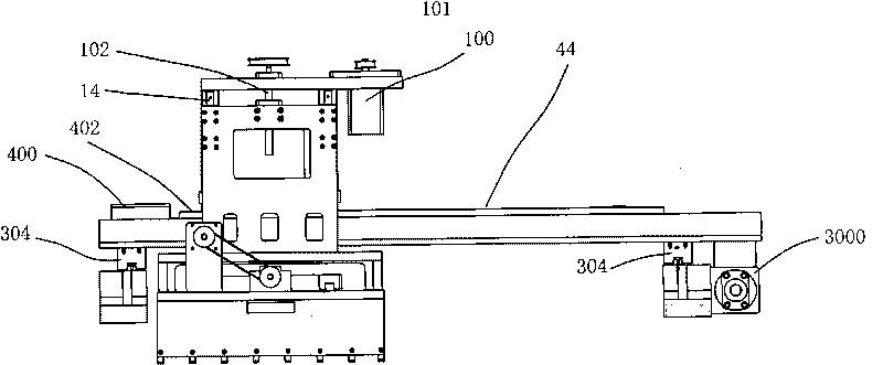
[0026] Wherein, the lifting displacement device 1 includes a lifting power mechanism 10 and a lifting base 12 driven by the lifting power mechanism 10 to move up and down along a lifting axis (ie, a Z axis).

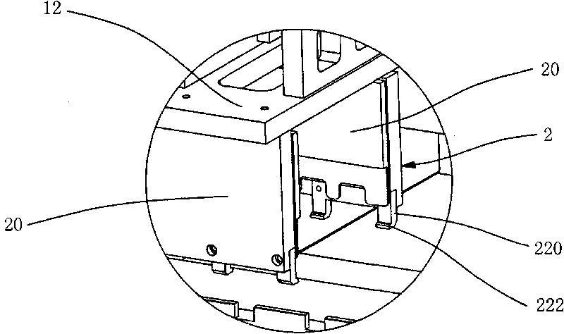
[0027] combine figure 2 As shown, the two claws 2 are arranged facing each other, and each claw 2 includes a base 20 and at least one protruding from the bottom edge of the base 20 toward the other claw 2 for supporting the workpiece from the bottom. minions22. The claw 22 includes an extension 220 connected to the base 20 and a supporting portion 222 bent from the end of the extension 220 toward the other claw 2 .

[002...


PUM


Abstract

The invention relates to a mechanical gripper of a wave-soldering unit, comprising a lifting displacement device, and a pair of gripper bodies driven by the lifting displacement device to lift and an opening-closing system used for driving the gripper bodies to realize the opening-closing movement, wherein the lifting displacement device comprises a lifting power mechanism and a lifting substrate driven by the lifting power mechanism to lift along a lifting shaft; the two gripper bodies are arranged over against each other; each gripper body comprises a base and a pawn extending towards the direction of another gripper body from the bottom edge of the base so as to support a workpiece from the bottom. The pawn of the mechanical gripper is utilized to support the workpiece from the bottom of the workpiece when the mechanical gripper grabs the workpiece; and due to the fact that the workpiece does not need to be clamped from the edge of the workpiece, the workpiece can not deform or is damaged due to clamping force.

Description

technical field [0001] The invention relates to the field of welding equipment, in particular to a wave soldering machine and its mechanical claws. Background technique [0002] In the wave soldering machine, it is necessary to use mechanical claws to grab workpieces such as PCB boards, and then move them to relevant stations for processing. Existing mechanical claws basically adopt the clamping method, and corresponding fixtures are provided to clamp the workpiece from the side edges of the PCB board and other workpieces during work, and generally need to be clamped on both sides. Due to the manufacturing and / or assembly errors of the equipment, it is easy to cause uneven force application at each clamping point, which can easily cause deformation of the workpiece, and even damage to the workpiece in serious cases. Contents of the invention [0003] The technical problem to be solved by the present invention is to provide a mechanical claw of a wave soldering machine, wh...

Claims


Application Information

Patent Timeline
Patent Type & Authority Applications(China)
IPC IPC(8): B23K3/08B25J15/02B25J15/08B23K1/08H05K3/34
Inventor 宋国明
Owner 深圳市诺斯达科技有限公司
Learn More