
Device for measuring width of single picosecond laser pulse

A pulse width and measurement device technology, applied in optics, nonlinear optics, instruments, etc., can solve the problems of increasing the difficulty of optical path adjustment, high loss, and complicated device, and achieve the improvement of time resolution, avoid excessive loss, and improve sensitivity. Effect

Inactive Publication Date: 2011-01-26
SHANGHAI INST OF OPTICS & FINE MECHANICS CHINESE ACAD OF SCI
View PDF0 Cites 0 Cited by
  • Summary
  • Abstract
  • Description
  • Claims
  • Application Information

AI Technical Summary

Problems solved by technology

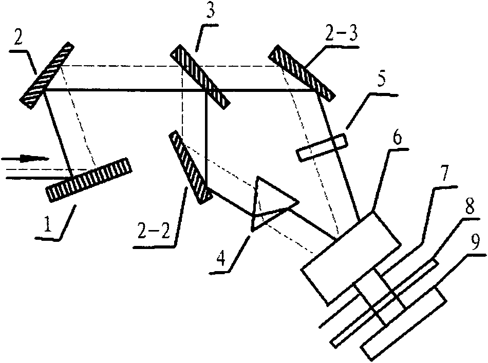
Although this device can realize a single measurement of the laser pulse width in the wavelength range of picoseconds to hundreds of picoseconds, the loss of the beam when it is grazing incident through the grating is very high. In addition, it is necessary to use a dove prism to invert the beam. The optical path difference is compensated by a quartz compensation block, which makes the device more complicated and virtually increases the difficulty of optical path adjustment

Method used


Image

  • Device for measuring width of single picosecond laser pulse
  • Device for measuring width of single picosecond laser pulse
  • Device for measuring width of single picosecond laser pulse

Examples


Embodiment Construction

[0019] The present invention will be further described below in conjunction with the embodiments and accompanying drawings, but the protection scope of the present invention should not be limited thereby.

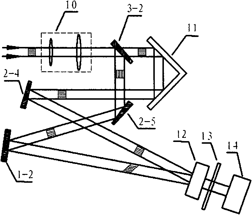
[0020] see first figure 2 , figure 2 It is a structural schematic diagram of a specific embodiment of a single picosecond laser pulse width measuring device of the present invention. As can be seen from the figure, the measuring device of the single picosecond laser pulse width of the present invention, the device embodiment is composed of a beam expander telescope 10, a beam splitter 3-2, a delay adjuster 11, a first reflector 2-4, a second reflector Mirror 2-5, reflective grating 1-2, KDP frequency doubling crystal 12, filter 13, CCD array 14 and oscilloscope (not shown in the figure), its positional relationship is: in the input direction of the laser pulse to be measured, the beam expander Telescope 10, beam splitter 3-2, the laser pulse beam to be measured is divid...


PUM


Abstract

The invention discloses a device for measuring the width of a single picosecond laser pulse. The device consists of a beam splitter, a delay adjustor, a first reflector, a second reflector, a reflection grating, a KDP frequency doubling crystal, a filter, a CCD array and an oscilloscope, which have the following position relationships that: the beam splitter is arranged in the input direction of the laser pulse to be measured; the laser pulse beam to be measured is split into a transmission beam and a reflection beam through the beam splitter; the transmission beam enters the KDP frequency doubling crystal through the delay adjustor and the first reflector; the reflection beam also enters the KDP frequency doubling crystal after passing through the second reflector and the reflection grating; and the two beams generate non-collinear related signals in the KDP frequency doubling crystal, and the related signals enter the CCD array through the filter and are finally displayed on the oscilloscope. The width of the measured pulse can be acquired through calculation. The device for measuring the width of the single picosecond laser pulse not only effectively improves the sensitivity ofthe measurement, but also enlarges the wavelength range of the measurable pulse.

Description

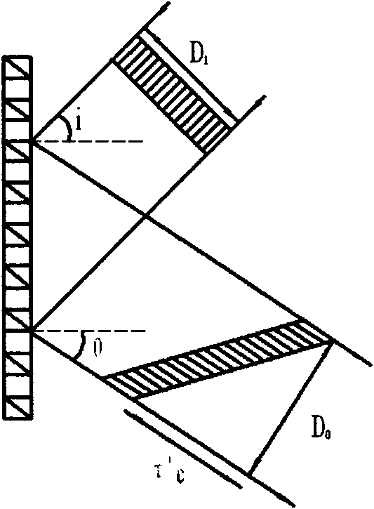
technical field [0001] The invention relates to a high-power ultrashort laser pulse, which is a measuring device for the width of a single ultrashort laser pulse. It uses a beam splitter to divide the laser beam to be measured into a reflected beam and a transmitted beam, and a reflective grating introduces a pulse into a beam of light. The wavefront is tilted (transverse time delay) and interacts non-collinearly with another beam of light in a frequency-doubling crystal to generate a correlated signal, enabling a single measurement of the picosecond laser pulse width. Background technique [0002] In recent years, with the emergence of new crystals and new lasers, research on optical parametric oscillators (OPO) and optical parametric amplifiers (OPA) has achieved many results, and with the development of chirped pulse amplification (CPA), high-energy A great breakthrough has been made in the generation of ultrashort laser pulses. Since the amplification of ultrashort puls...

Claims


Application Information

Patent Timeline
Patent Type & Authority Patents(China)
IPC IPC(8): G01J11/00G02F1/35
Inventor 张福领谢兴龙孙美智毕群玉林尊琪
Owner SHANGHAI INST OF OPTICS & FINE MECHANICS CHINESE ACAD OF SCI
Learn More