
Molten salt tube-shell type steam generating device and method

A steam generating device, shell-and-tube technology, applied in the field of molten salt shell-and-tube steam generating device, can solve the problem that the heat storage function of molten salt working medium and molten salt tank is not fully utilized, and the structure of the serpentine heat-absorbing pipe body is complicated , Heat transfer process parameters are not easy to control and other problems, to achieve the effect of stable heat exchange and evaporation process, convenient for large-scale production, and beneficial to cost control

Inactive Publication Date: 2011-08-31
SOUTH CHINA UNIV OF TECH +1
View PDF0 Cites 0 Cited by
  • Summary
  • Abstract
  • Description
  • Claims
  • Application Information

AI Technical Summary

Problems solved by technology

In large-scale solar energy medium and high temperature heat utilization systems such as solar thermal power generation, there are some defects in the molten salt casing steam generator: (1) because the heat energy absorbed by the pipe wall is directly transmitted to the water working medium in the pipe through the molten salt in the casing, The molten salt mainly plays the role of heat transfer, and because the heat storage capacity of the molten salt in the casing is small, the heat storage function of the molten salt working fluid and the molten salt tank has not been fully utilized; (2) due to the real-time changes of the solar radiation outside the casing , the internal energy change of the molten salt in the casing is coupled with the evaporation process, and the parameters of the entire heat transfer process and water vapor of the casing system are not easy to control; (3) Due to the complex structure of the serpentine heat-absorbing tube body, the processing of the casing is difficult , so it is difficult to scale up

Method used


Image

  • Molten salt tube-shell type steam generating device and method
  • Molten salt tube-shell type steam generating device and method

Examples


Embodiment

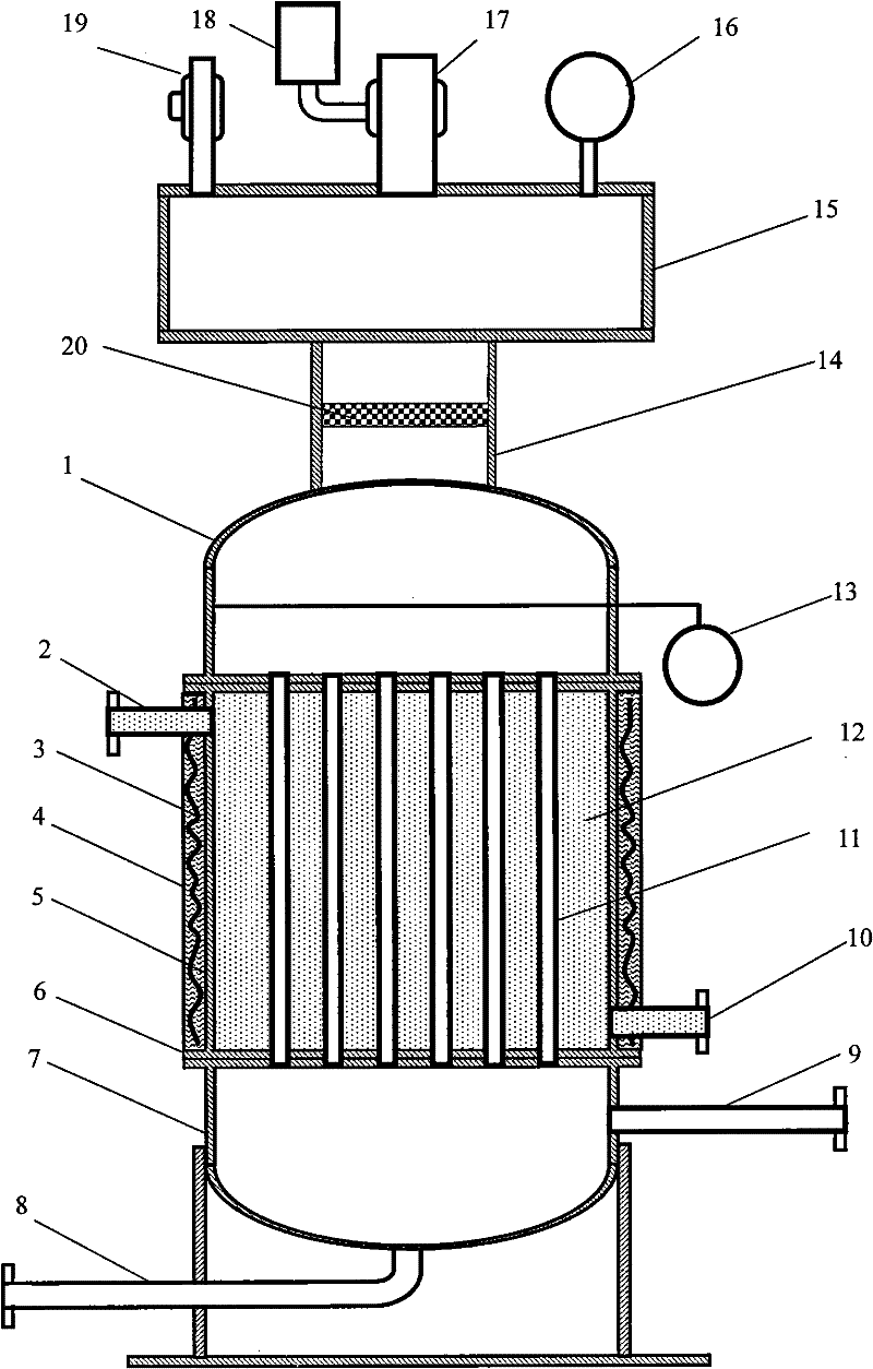
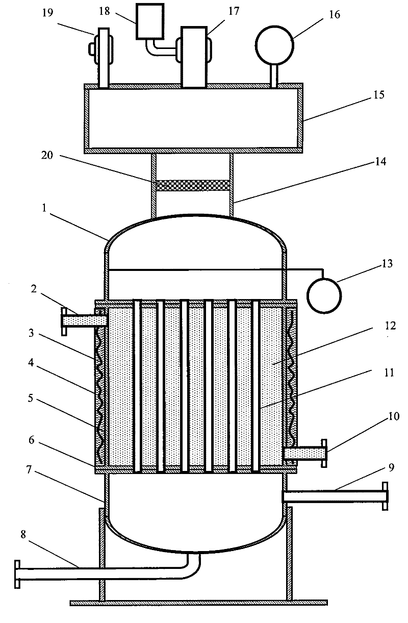
[0032] In this embodiment, a molten salt shell-and-tube steam generating device has a structure such as figure 1 As shown, it includes a shell-and-tube heat exchanger, a steam separation output assembly and a heating and heat preservation assembly. The steam separation output assembly is arranged on the top of the shell-and-tube heat exchanger, and the heating and insulation assembly is arranged on the outside of the container wall of the shell-and-tube heat exchanger; The shell-and-tube heat exchanger includes a top tube box 1, a tube body 5 and a bottom tube box 7 arranged sequentially from top to bottom. A tube bundle 11 is arranged inside the tube body 5, and the two ends of the tube bundle 11 pass through the tube sheet 6 and the tube body 5 respectively. Fixed connection, the gap between the tube bundles 11 in the pipe body 5 is filled with molten salt 12; the outer side of the pipe body 5 is provided with a molten salt inlet pipe 10 and a molten salt outlet pipe 2, and t...


PUM


Abstract

The invention provides a molten salt tube-shell type steam generating device and a molten salt tube-shell type steam generating method. The device comprises a tube-shell type heat exchanger, a steam separation output component and a heating and heat preservation component, wherein the steam separation output component is arranged on the top of the tube-shell type heat exchanger, and the heating and heat preservation component is arranged on the outer side of the container wall of the tube-shell type heat exchanger; the tube-shell type heat exchanger is provided with a top tube box, a tube body and a bottom tube box in sequence from top to bottom, wherein the inside of the tube body is provided with tube bundles of which both ends are fixedly connected with the tube body by tube plates, and the gaps between the tube bundles are filled with molten salt; and the outer side of the tube body is provided with a molten salt inlet tube and a molten salt outlet tube, and the bottom tube box isprovided with a water inlet tube and a water outlet tube. The method comprises the following steps of: pre-heating the tube body; and orderly performing molten salt filling, hot water filling, and steam separating and outputting. The device has the advantages of big effective heat storage capacity, long-term stable operation, and relatively low manufacturing cost and maintenance cost, and can meet the requirements on large-scale solar mid- and high-temperature heat utilization in industry.

Description

technical field [0001] The invention relates to solar medium and high temperature heat utilization technology, in particular to a molten salt shell-and-tube steam generating device and method. Background technique [0002] As a clean energy technology with low cost and large-scale prospects, solar energy medium and high temperature heat utilization technology is a strategic new energy technology for the sustainable development of my country's national economy. The medium and high temperature heat utilization system of solar energy is mainly composed of a concentrating system, a heat absorption system, a heat storage system and a heat utilization device. Since solar energy is intermittent and unstable, it is difficult to meet the requirements of large-scale continuous and stable energy supply in industrialization. Therefore, it is necessary to develop efficient heat storage technology to effectively solve the problems of solar energy conversion, transmission and storage. [...

Claims


Application Information

Patent Timeline
Patent Type & Authority Patents(China)
IPC IPC(8): F22B1/06
Inventor 杨建平陆建峰丁静杨晓西
Owner SOUTH CHINA UNIV OF TECH
Learn More