
Rotor terminal structure of three-phase permanent magnet synchronous motor

A three-phase synchronous, motor rotor technology, applied in the direction of synchronous machine parts, etc., can solve the problems of large stator and rotor size, material cost, etc.

Inactive Publication Date: 2010-04-21
WUXI NEW GREAT POWER ELECTRICAL MACHINE
View PDF5 Cites 1 Cited by
  • Summary
  • Abstract
  • Description
  • Claims
  • Application Information

AI Technical Summary

Problems solved by technology

In this way, if the motor is required to output the same torque, a larger stator and rotor size is required, so more material costs will be consumed

Method used


Image

  • Rotor terminal structure of three-phase permanent magnet synchronous motor
  • Rotor terminal structure of three-phase permanent magnet synchronous motor

Examples


Embodiment Construction

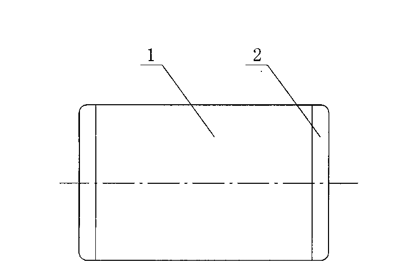
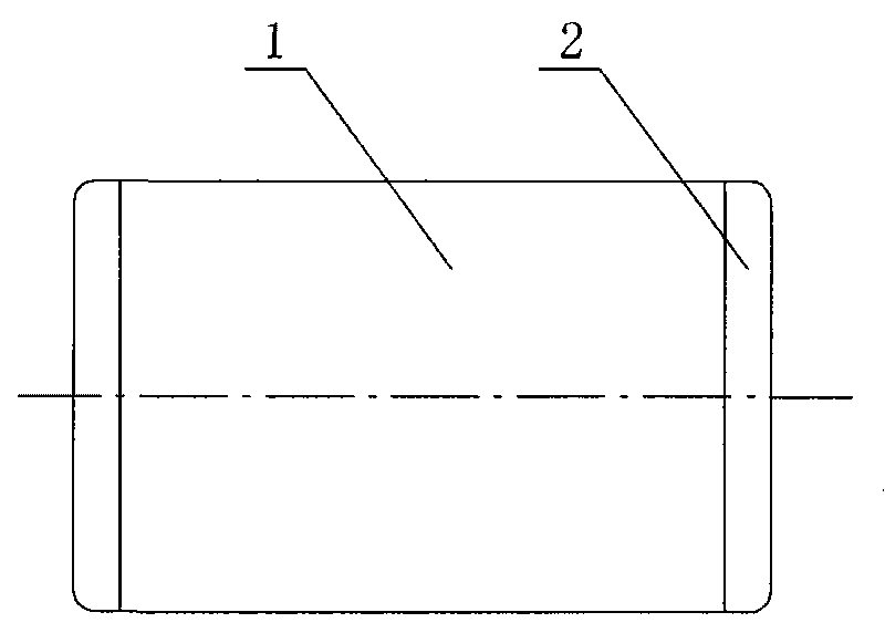
[0011] Such as figure 1 As shown, the end structure of the permanent magnet three-phase synchronous motor rotor 1 according to the present invention adopts non-magnetic materials at the end 2 .

[0012] The use of non-magnetic materials at the end of the motor rotor can reduce the reactance at the end of the motor, which is equivalent to reducing the coefficient at the end to improve the output performance index of the motor. The overcurrent of an ordinary motor is 1.5 times, and the overtorque The overcurrent of the rare earth permanent magnet motor with non-magnetic materials at the end can reach 3 times, and the overtorque can reach more than 3.5 times. Therefore, in actual use, one frame size can be reduced to use, and the cost of non-ferrous metal materials such as iron and copper can be saved by more than 30%.


PUM


Abstract

The invention discloses a rotor terminal structure of a three-phase permanent magnet synchronous motor. A non-magnetic material is adopted at the rotor terminal part of the motor, so the reactance of the terminal part of the motor is reduced, namely, the coefficient of the terminal part is reduced. As a result, the output performance index of the motor is improved. Compared with the overcurrent and overtorque of the common motor which are 1.5 times and 2.2 times respectively, the overcurrent and the overtorque of rear-earth permanent magnet motor of which the terminal part using the non-magnetic material reach 3 times and more than 3.5 times respectively. In actual use, a machine seat size can be reduced and cost of non ferrous metal materials such as iron and copper can be saved by over 30 percent.

Description

technical field [0001] The invention relates to a permanent magnet three-phase synchronous motor, in particular to a rotor end structure of a permanent magnet three-phase synchronous motor. Background technique [0002] The rotor end of the rare earth permanent magnet three-phase synchronous motor, due to the characteristics of magnetic permeability, has a large reactance and reduces its current. In this way, if the motor is required to output the same torque, a larger stator and rotor size is required, so more material costs are consumed. Contents of the invention [0003] The purpose of the present invention is to provide a rotor end structure of a permanent magnet three-phase synchronous motor, which solves the problem that the starting current of similar products is too large and needs to add a matching frequency converter to start the motor. [0004] The purpose of the present invention is to realize through the following technical solutions: [0005] The rotor end ...

Claims


Application Information

Patent Timeline
IPC IPC(8): H02K21/02
Inventor 徐荣祖马天龙
Owner WUXI NEW GREAT POWER ELECTRICAL MACHINE
Learn More