
A three-phase separator for an anaerobic reactor

A three-phase separator and anaerobic reactor technology, applied in the field of three-phase separators, can solve the problems of affecting sludge settlement, complex structure, mutual interference, etc., and achieve the effects of easy floating removal, increasing flow area, and reducing pressure.

Inactive Publication Date: 2011-12-21
NANKAI UNIV
View PDF0 Cites 4 Cited by
  • Summary
  • Abstract
  • Description
  • Claims
  • Application Information

AI Technical Summary

Problems solved by technology

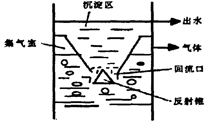
[0005] Conventional three-phase separators mainly have the following problems: the inflow port and the return port are overlapped, so that a large amount of returning sludge and the rising water flow interfere with each other, and at the same time, the gas that is not completely separated will enter the sedimentation area with the sludge, affecting The sedimentation of the sludge is hindered, and the high sludge concentration in the reactor cannot be maintained.
[0006] The inlet and return ports of the improved three-phase separator are separated, which can improve the sedimentation efficiency, but there is a problem of complex structure. If the design is not reasonable, the inlet water may enter the sedimentation area from the return port, resulting in difficult sludge return to reaction area

Method used


Image

  • A three-phase separator for an anaerobic reactor
  • A three-phase separator for an anaerobic reactor
  • A three-phase separator for an anaerobic reactor

Examples


Embodiment 1

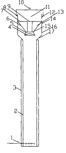
[0023] The structure of the present invention is as described above, wherein the diameter of the reactor shell 2 is 3 meters, the diameter of the three-phase separator outer cylinder 16 is 4 meters, the connecting cone 17 and the horizontal angle are 45 °, the conical guide cylinder 6 and the horizontal The included angle is 60°. The diameter of the reflection cone 4 is 0.6 meters, the diameter of the cylindrical guide tube is 0.3 meters, the ratio of the diameter of the cylindrical guide tube 9 to the bottom diameter of the conical sedimentation zone 6 is 0.7, and the height of the solid-liquid separation zone 11 is 0.6 meters.

Embodiment 2

[0025] The structure of the present invention is as described above, wherein the diameter of the reactor shell 2 is 8 meters, the diameter of the three-phase separator outer cylinder 16 is 10 meters, the connecting cone 17 and the horizontal angle are 45 °, the conical guide cylinder 6 and the horizontal The included angle is 45°. The diameter of the reflection cone 4 is 1.4 meters, the diameter of the cylindrical guide tube is 0.8 meters, the ratio of the diameter of the cylindrical guide tube 9 to the bottom diameter of the conical sedimentation zone 6 is 0.7, and the height of the solid-liquid separation zone 11 is 1 meter.


PUM


Abstract

The invention relates to a three-phase separator for an upflow anaerobic reactor, which consists of a reflective cone, a conical guide tube on the reflective cone, a cylindrical guide tube in the center of the conical guide tube and a gas cover at the upper end Composition, the outer side of the top of the cone-shaped guide tube is provided with an exhaust pipe, the top of the gas hood is also provided with an exhaust pipe, and an annular passage is provided between the cone-shaped guide tube and the cylindrical guide tube There is an annular overflow channel between the air cover and the top air cover. The invention separates the inflow port and the return port of the muddy water by adding a cylindrical guide tube in the conical guide tube. The structure is simple and can solve the problem of three-phase separator inflow The coincidence problem of the outlet and the return outlet can be improved, the separation effect of gas, liquid and solid can be improved, the liquid flow in the sludge settlement area can be kept stable, and the wastewater removal efficiency of the anaerobic reactor can be improved.

Description

technical field [0001] The invention relates to a three-phase separator used in an upflow anaerobic reactor, belonging to the technical field of water treatment. Background technique [0002] The upflow anaerobic reactor has the advantages of simple structure, high organic load, and wide adaptability, and has been widely used in the treatment of various industrial wastewater. [0003] Industrial wastewater enters the anaerobic reactor from the bottom of the reactor through the water distributor, and fully contacts with anaerobic microorganisms in the reaction zone, biochemical reactions occur to generate biogas, and a large number of air bubbles are generated. The air bubbles carry water and sludge to form gas-liquid-solid The mutually inclusive mixture rises together into the three-phase separator, and first collides with the reflector cone, causing the separation of mud and gas. The degassed mud-water mixture enters the sedimentation zone from the inlet for mud-water separ...

Claims


Application Information

Patent Timeline
Patent Type & Authority Patents(China)
IPC IPC(8): B01D19/00B01D21/02C02F3/28
Inventor 郭晓燕
Owner NANKAI UNIV
Learn More