
Sliding structure and electronic device applied by same

A sliding structure and electronic device technology, which is applied to the installation of support structures, electrical equipment shells/cabinets/drawers, electrical components, etc., can solve the problems of reduced manufacturing process quality, waste of manufacturing process costs, inconvenient structure and use, etc., to achieve improvement Good rate, high structural reliability, cost reduction effect

Inactive Publication Date: 2010-03-31
INVENTEC CORP
View PDF0 Cites 6 Cited by
  • Summary
  • Abstract
  • Description
  • Claims
  • Application Information

AI Technical Summary

Problems solved by technology

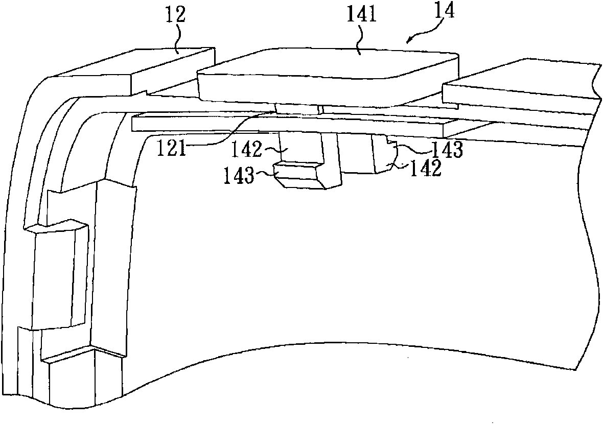
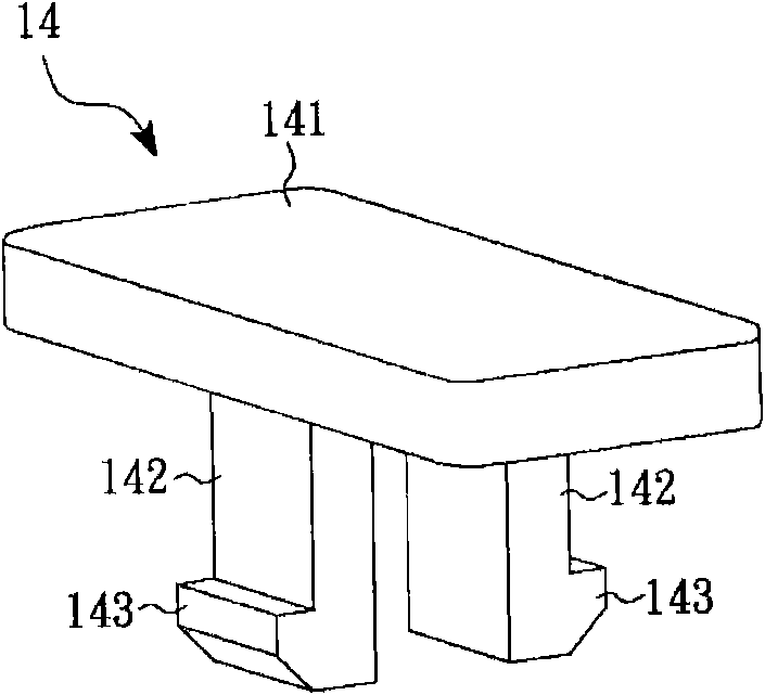
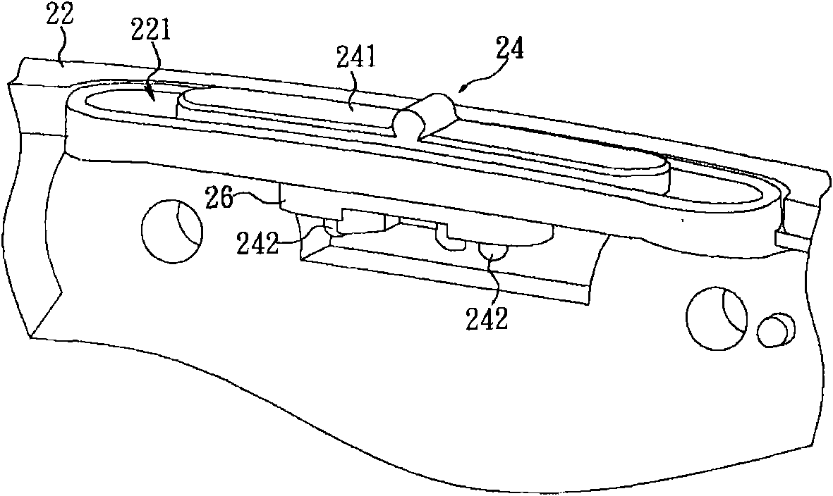
Because the structural reliability of the sliding structure 24 and the housing 22 can be improved by the fixed structure 26 adhered to the sliding structure 24, however, because an additional process of heat fusion (or welding) must be applied during the assembly process , thus reducing the good rate of the manufacturing process (process), and once the processing fails, because the hot melt (or welding) manufacturing process is an irreversible processing method, it is easy to cause waste of process cost
[0005] It can be seen that the above-mentioned existing sliding structure and the electronic device applied thereto obviously still have inconvenience and defects in structure and use, and need to be further improved urgently.

Method used


Image

  • Sliding structure and electronic device applied by same
  • Sliding structure and electronic device applied by same
  • Sliding structure and electronic device applied by same

Examples


Embodiment Construction

[0040] In order to further explain the technical means and effects that the present invention takes to achieve the intended purpose of the invention, below in conjunction with the accompanying drawings and preferred embodiments, the specific implementation, structure, Features and their functions are described in detail below.

[0041] The aforementioned and other technical contents, features and effects of the present invention will be clearly presented in the following detailed description of preferred embodiments with reference to the drawings. A sliding structure according to a preferred embodiment of the present invention and an electronic device for its application will be described below with reference to related drawings, wherein the same components will be described with the same reference numerals.

[0042] see image 3 Shown is a partial schematic diagram of an electronic device disclosed in the present invention. In an electronic device disclosed in a preferred e...


PUM


Abstract

The invention relates to a sliding structure and an electronic device applied by the same. The sliding structure is matched with a shell and comprises a plate body, a column body and a limit piece, wherein at least one part of the plate body is exposed out of the shell, the column body is connected with the plate body and is provided with a concave part; the limit piece is provided with a bolt andat least one clip, the bolt is inserted into the concave part, and the clip is clamped at the periphery of the column body. The electronic device comprises a shell, a plate body, a column body and alimit piece, wherein the shell is provided with a groove, at least one part of the plate body is exposed out of the shell, the column body is connected with the plate body and provided with a concavepart, the column body is arranged in the groove in a penetrating way and slides in the groove, the limit piece is provided with a bolt and at least one clip, the bolt is inserted in the concave part,and the clip is clamped at the periphery of the column body. On the premise of not increasing the complexity of the manufacture procedure, the sliding structure is stably connected to the shell of theelectronic device by using a structural fixing mode, the structure reliability can be improved without increasing the cost incidence of the product, the excellent rate of the manufacture procedure can be improved, and the product cost can be lowered.

Description

technical field [0001] The present invention relates to a sliding structure and an electronic device for its application, in particular to a structural fixing method to firmly connect the sliding structure to the housing of the electronic device, which can improve the structural reliability without increasing the product cost burden The sliding structure and its applied electronic device. Background technique [0002] In an electronic device, in addition to the commonly used push button, as the functions of the electronic device gradually increase, the sliding key controlled by sliding has become one of the necessary components of the electronic device. [0003] For example, see Figure 1A and Figure 1B as shown, Figure 1A It is a schematic diagram of a partial structure of an existing known electronic device with a sliding structure, Figure 1B for correspondence Figure 1A A schematic diagram of the sliding structure shown in . The housing 12 of this prior known elect...

Claims


Application Information

Patent Timeline
IPC IPC(8): H05K5/02H05K7/14H05K5/00
Inventor 王力戈林宜璇
Owner INVENTEC CORP
Learn More