Eureka AIR delivers breakthrough ideas for toughest innovation challenges, trusted by R&D personnel around the world.

Temperature monitoring for circuit breakers

A technology of power switch and switch, which is applied in the direction of temperature control, electric temperature control, electrical components, etc., and can solve the problem of undisplayed power semiconductor switch module configuration, etc.

Active Publication Date: 2010-03-24
BAUMULLER NURNBERG GMBH
View PDF3 Cites 6 Cited by
  • Summary
  • Abstract
  • Description
  • Claims
  • Application Information

AI Technical Summary

Problems solved by technology

However, this company document does not show how to efficiently determine and monitor temperature for configurations with multiple power semiconductor switching modules, as is often the case in inverters

Method used


Image

  • Temperature monitoring for circuit breakers
  • Temperature monitoring for circuit breakers
  • Temperature monitoring for circuit breakers

Examples


Embodiment Construction

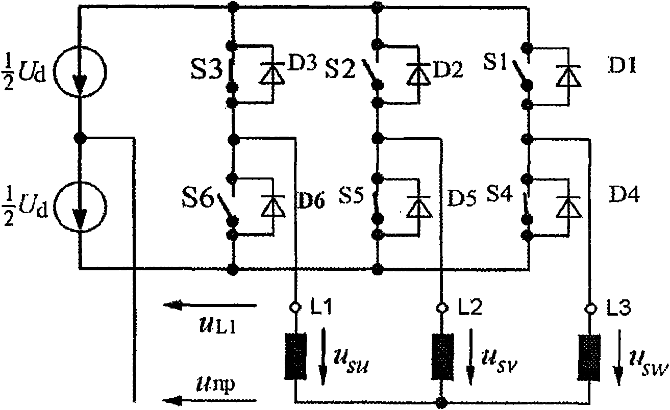
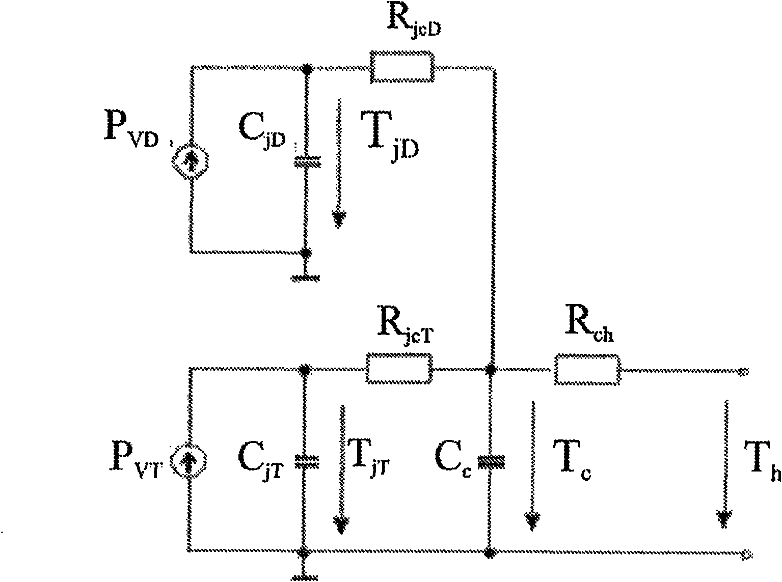
[0021] according to figure 1 , six semiconductor power switches S1-S6 are directly assembled on the slightly elongated cooling body that is rectangular. They are arranged in parallel or next to each other in two rows S1-S3 and S4-S6, each row extending along the longitudinal direction of the cooling body on one half of the cooling body. exist figure 2 , the detailed composition of the switches S1-S6 is shown in a manner well known in the art (see pages 68, 69 and 139 of the aforementioned SEMIKRON document). Notably, each power switch S1-S6 has been assigned a freewheeling or reverse diode D1-D6. Between every two power switches S1 , S4 ; S2 , S5 ; S3 , S6 connected in series and each generating a phase U, V, W of a three-phase current system, a sinusoidal alternating voltage is measured and supplied, for example, to The coils L1, L2, L3 of the stator of the three-phase motor.

[0022] according to figure 1 , the current measurement 4 is carried out in the three phase be...


PUM


Abstract

The invention relates to a method for determining and / or monitoring the temperatures of at least two electronic power switches, particularly semiconductor circuit breakers, which are coupled to or arranged on a common cooling body, wherein the temperature determination and / or monitoring occurs based on a temperature model associated with a switch each, switch and operating parameters and temperature measurement values being processed in said model for calculating the temperature and / or a temperature difference inside the respective switch, wherein a temperature measurement value from a temperature sensor is used as an input parameter for the temperature model, the sensor being disposed spatially at the center between the at least two switches and having a heat-transmitting connection to the cooling body. The invention further relates to an electronic power temperature-providing switch arrangement, particularly converters for electric drives or other converters, for performing the method according to any one of the preceding claims.

Description

technical field [0001] The invention relates to a method for determining and / or monitoring the temperature of at least two electronic power switches, in particular made of semiconductors. Furthermore, the two switching modules are coupled to or arranged on a common heat sink. The temperature determination and / or monitoring is carried out on the basis of a temperature model which is respectively assigned to a switch or switch module. Switches and operating parameters are processed in the temperature model assigned to a switch in order to calculate the temperature and / or temperature difference in the associated switch. [0002] The invention also relates to an arrangement of electronic power switches providing temperature, which may in particular be an inverter or other converter supplying an electric drive. This arrangement is suitable for carrying out the method described above and has two or more switches, in particular semiconductor power switches, which are coupled to or ...

Claims


Application Information

Patent Timeline
Patent Type & Authority Applications(China)
IPC IPC(8): G05D23/19
CPCG05D23/1935H02M7/003H02M7/53871H02M7/5387
Inventor 蒋金生
Owner BAUMULLER NURNBERG GMBH
Why Eureka
Eureka Blog
Learn More