Eureka AIR delivers breakthrough ideas for toughest innovation challenges, trusted by R&D personnel around the world.

Physical vapor deposition equipment and physical vapor deposition process

A technology of physical vapor deposition and equipment, which is applied in metal material coating process, ion implantation plating, coating, etc., can solve the uneven temperature distribution of the substrate 4', affect the subsequent process of the substrate 4', and substrate heating The problem of poor uniformity can eliminate the problem of substrate temperature unevenness, improve the effect of degassing, and improve the effect of uniformity

Active Publication Date: 2016-04-20
BEIJING NAURA MICROELECTRONICS EQUIP CO LTD
View PDF4 Cites 0 Cited by
  • Summary
  • Abstract
  • Description
  • Claims
  • Application Information

AI Technical Summary

Problems solved by technology

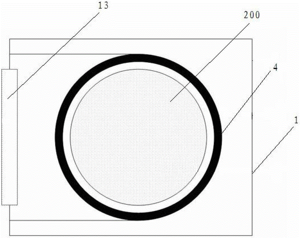
[0004] Figure 8 is a top view of physical vapor deposition equipment in the prior art, from Figure 8 It can be seen from the figure that the substrate transfer port 11' on the side wall of the reaction chamber will cause the heat reflected from the inner wall of the reaction chamber to the substrate 4' to be uneven, resulting in uneven temperature distribution of the substrate 4', Subsequent process affecting substrate 4'
In other words, since there is a transmission port on the side wall of the chamber, the structure of the chamber is not completely symmetrical, so the light reflected by the chamber wall on the side with the opening to the substrate is smaller than that reflected by the chamber wall on the side without the opening. The light on the substrate, which causes the heat reflected by the inner wall of the chamber to the substrate to be unequal, which in turn leads to poor heating uniformity in the circumferential direction of the substrate.

Method used


Image

  • Physical vapor deposition equipment and physical vapor deposition process
  • Physical vapor deposition equipment and physical vapor deposition process
  • Physical vapor deposition equipment and physical vapor deposition process

Examples


Embodiment Construction

[0051] The following describes in detail the embodiments of the present invention, examples of which are illustrated in the accompanying drawings, wherein the same or similar reference numerals refer to the same or similar elements or elements having the same or similar functions throughout. The embodiments described below with reference to the accompanying drawings are exemplary, and are intended to explain the present invention and should not be construed as limiting the present invention.

[0052] In the description of the present invention, it should be understood that the terms "center", "longitudinal", "lateral", "length", "width", "thickness", "upper", "lower", "front", " Rear", "left", "right", "vertical", "horizontal", "top", "bottom", "inside", "outside", "clockwise", "counterclockwise", etc. The relationship is based on the orientation or positional relationship shown in the drawings, which is only for the convenience of describing the present invention and simplify...


PUM


Abstract

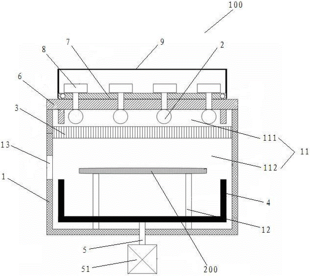
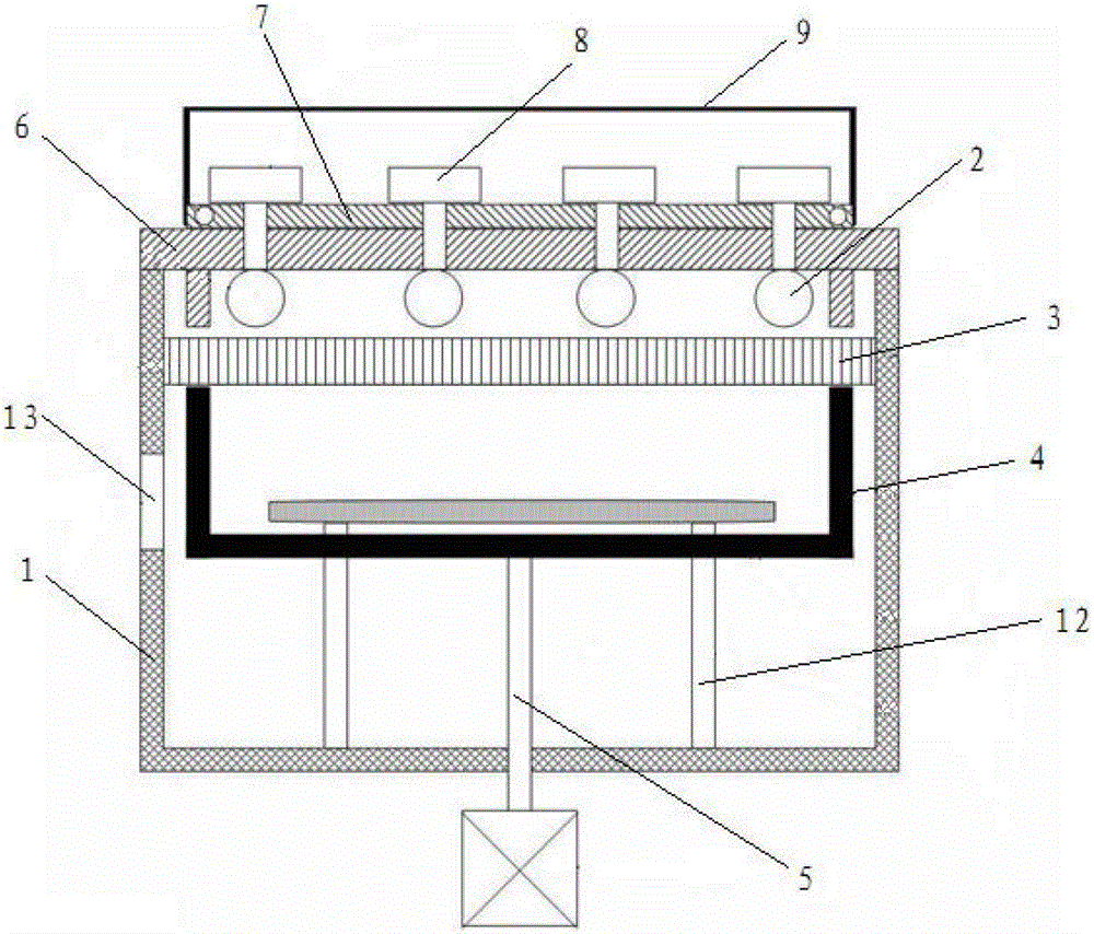
The invention discloses a physical vapor deposition device which comprises a reaction chamber, wherein the reaction chamber comprises a medium window arranged in the reaction chamber and used for dividing the reaction chamber into an upper chamber and a lower chamber, a substrate support component in the lower chamber, a heating component arranged on the top wall of the upper chamber and used for heating a to-be-processed substrate, a substrate sending port arranged on the side wall of the lower chamber and used for sending out the processed substrate from the lower chamber or sending the to-be-processed substrate in the lower chamber, and a heating constraint bucket arranged in the lower chamber and can be lifted in the lower chamber through a lifting mechanism. The medium window has light transmission and is used for sealing the lower chamber. The physical vapor deposition equipment disclosed by the invention is capable of greatly improving the uniformity when the substrate is heated and improving the degassing effect of the substrate. The invention further discloses a physical vapor deposition process.

Description

technical field [0001] The invention relates to the field of semiconductor processing, in particular to a physical vapor deposition device and a physical vapor deposition process using the device. Background technique [0002] The copper interconnect physical vapor deposition process mainly includes four processes: 1) degassing; 2) pre-cleaning; 3) Ta(N) deposition; 4) Cu deposition. For the degassing process, the substrate is mainly heated to a certain temperature in the degassing chamber to remove the water vapor and other volatile impurities adsorbed on the substrate. In the actual degassing process, the heating uniformity of the degassing process is required. Very high, if the heating is not uniform, volatile impurities may remain in some areas of the substrate, which will affect the subsequent process, and local temperature unevenness may even damage the substrate. [0003] Figure 7 is a cross-sectional view of physical vapor deposition in the prior art. 7' is the he...

Claims


Application Information

Patent Timeline
Patent Type & Authority Patents(China)
IPC IPC(8): C23C14/22C23C14/02
Inventor 边国栋
Owner BEIJING NAURA MICROELECTRONICS EQUIP CO LTD
Why Eureka
Eureka Blog
Learn More