
Driving magnitude control device of differential quadrature phase shift keying transmitter and method

A phase-shift keying and differential four-phase technology, applied in electromagnetic transmitters, electromagnetic wave transmission systems, electrical components, etc., can solve problems such as complex control circuits, large control loops, and OSNR costs, and achieve the effect of simplifying the complexity

Active Publication Date: 2010-03-17
ZTE CORP
View PDF0 Cites 12 Cited by
  • Summary
  • Abstract
  • Description
  • Claims
  • Application Information

AI Technical Summary

Problems solved by technology

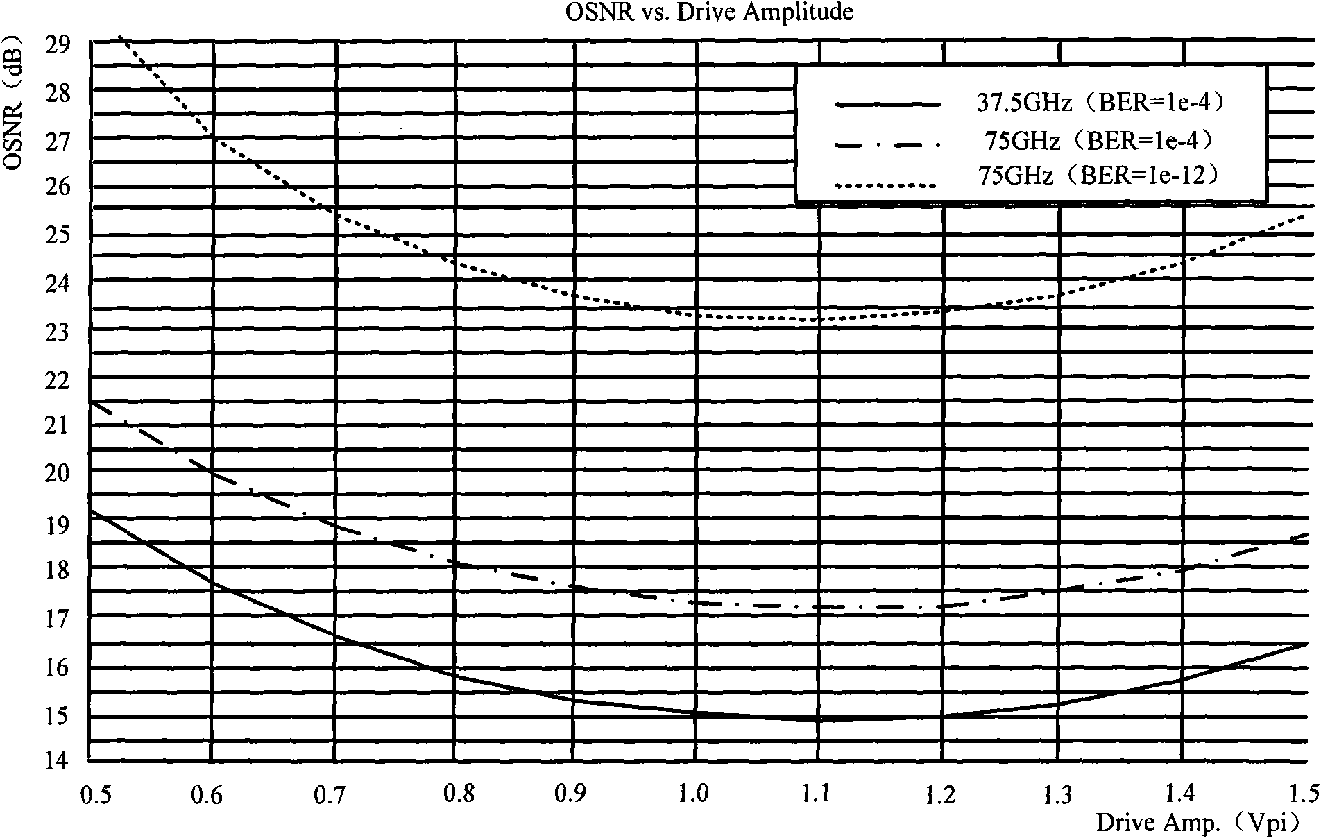
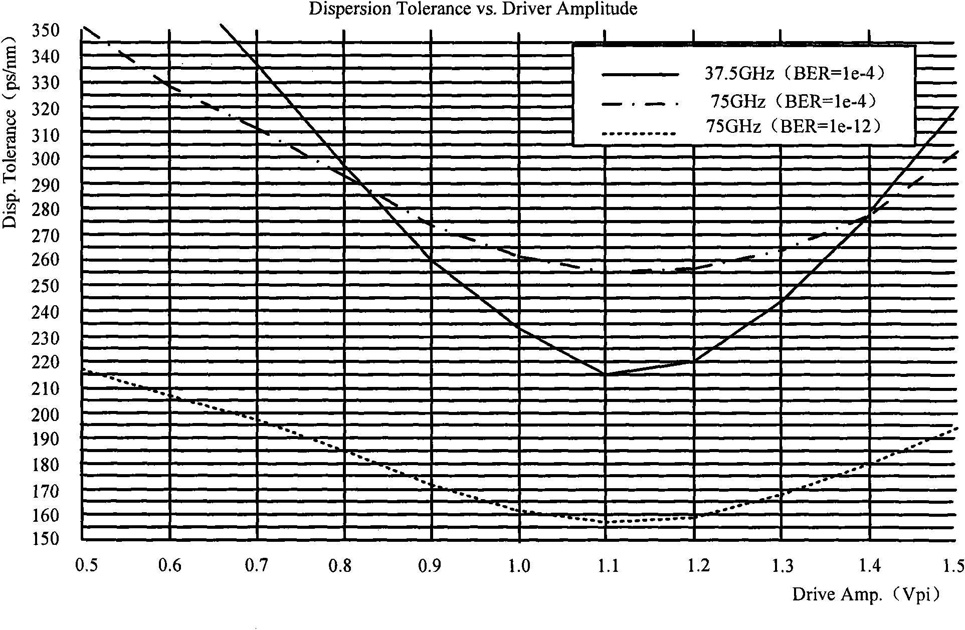
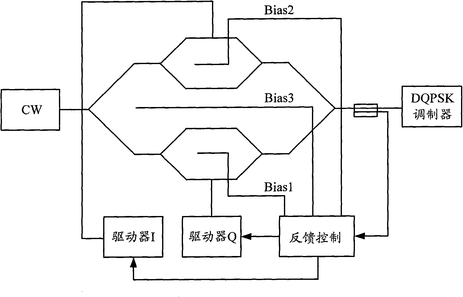
[0007] The disadvantage of the prior art is: since the DQPSK transmitter needs to control the three bias points of the modulator, the control circuit is relatively complicated. , the control loop will be very large, and adding a pilot signal will introduce a certain OSNR cost

Method used


Image

  • Driving magnitude control device of differential quadrature phase shift keying transmitter and method
  • Driving magnitude control device of differential quadrature phase shift keying transmitter and method
  • Driving magnitude control device of differential quadrature phase shift keying transmitter and method

Examples


Embodiment 1

[0035] Figure 4 It is a schematic diagram of the feedback control of the driver in the direct compensation mode. In the figure, the driver has three stages, and each stage can be considered as a MOSFET (MetalOxide Semiconductor Field Effect Transistor, Metal Oxide Semiconductor Field Effect Transistor). VD3 is the MOSFET of the third stage. Drain voltage, VD2 is the drain voltage of the MOSFET in the second stage, and VD1 is the drain voltage of the MOSFET in the first stage.

[0036] DC-DC is a switching power supply converter, and Vin is the input voltage of the DC-DC power conversion.

[0037] TEMP SENSOR is a temperature sensor.

[0038] VG is the gate voltage of the MOSFET.

[0039] ADC is an analog-to-digital converter (Analog to Digital Converter).

[0040] As shown in the figure, in the direct compensation mode, the amplitude of this type of driver is related to VD3, so the temperature of the driver can be detected by using a temperature sensor, and then the temperat...

Embodiment 2

[0050] Figure 6 It is a schematic diagram of driver feedback control under indirect compensation mode. The driver in the figure has three stages, VD3 is the drain voltage of the MOSFET in the third stage, VD2 is the drain voltage of the MOSFET in the second stage, and VD1 is the drain voltage of the first stage. MOSFET drain voltage.

[0051] DC-DC is a switching power supply converter, and Vin is the input voltage of the DC-DC power conversion.

[0052] Current Monitor is a current detector.

[0053] VG is the gate voltage of the MOSFET.

[0054] ADC is an analog-to-digital converter (Analog to Digital Converter).

[0055] As shown in the figure, in the indirect compensation mode, if the amplitude of the driver changes due to the influence of temperature, the current of another signal in the device flowing through VD3 will change, so it can be detected indirectly by detecting whether the current of VD3 changes. to see if the amplitude of the drive has changed. If a chan...


PUM


Abstract

The invention discloses a driving magnitude control device of a differential quadrature phase shift keying transmitter and a method. The method comprises the following steps: a differential quadrature phase shift keying modulator modulates the optical signals which are not added with modulating signals and which are emitted by a continuous spectroscopic light source; a feedback control unit of the modulator is connected with a first offset point, a second offset point and a third offset point and controls the first offset point, the second offset point and the third offset point according to part of the optical signals modulated by the differential quadrature phase shift keying modulator; the driving amplitude of a driver I is controlled according to the temperature change of the driver I; and the driving amplitude of the driver Q is controlled according to the temperature change of the driver Q. The adoption of the invention can simplify the complex degree of the control loop of the differential quadrature phase shift keying transmitter, and no pilot frequency signal needs to be added on the amplitude of the driver, thus generating no redundant optical signal to noise ratio cost.

Description

technical field [0001] The invention relates to communication equipment, in particular to a driving range control device and method of a differential quadrature phase-shift keying transmitter. Background technique [0002] Many new modulation techniques are applied in optical communication, such as: DPSK (Diffential Phase Shift Keying, differential phase shift keying), DQPSK (Differential Quadrature Phase Shift Keying, differential quadrature phase shift keying), etc., and DQPSK coding is more due to It can reduce the requirements on the speed, dispersion and PMD (Polarization Mode Dispersion, Polarization Mode Dispersion) of electrical devices, and occupies an important position in 40G optical communication systems. When the DQPSK transmitter uses MZM (Mach-Zender Modulator, Mach-Zehnder modulator) modulation to generate NRZ-DQPSK (Non-Return-to-Zero-DQPSK, non-return-to-zero-DQPSK) signal, the influence ratio of the amplitude change of the driver is NRZ-DPSK is much large...

Claims


Application Information

Patent Timeline
Patent Type & Authority Applications(China)
IPC IPC(8): H04B10/155H03K19/003H04B10/50H04B10/556
CPCH04B10/50572H04B10/5561H04B10/5053H04B10/5057H04B10/50575
Inventor 崔平朱晓宇
Owner ZTE CORP
Learn More