
Method for manufacturing LED indicator light

A technology of LED indicator light and manufacturing method, which is applied to parts of lighting devices, semiconductor devices of light-emitting elements, lighting and heating equipment, etc., can solve problems such as cumbersome production processes and hidden dangers in product quality, and achieve reduction of manufacturing processes and improvement Product reliability and cost reduction effects

Inactive Publication Date: 2010-03-17
中外合资江苏稳润光电有限公司
View PDF0 Cites 6 Cited by
  • Summary
  • Abstract
  • Description
  • Claims
  • Application Information

AI Technical Summary

Problems solved by technology

[0003] The purpose of the present invention is to provide a method for manufacturing LED indicator lights, which overcomes the disadvantages of cumbersome production processes and hidden dangers in product quality.

Method used


Image

  • Method for manufacturing LED indicator light

Examples


Embodiment Construction

[0014] The present invention will be further described below in conjunction with the accompanying drawings and specific embodiments.

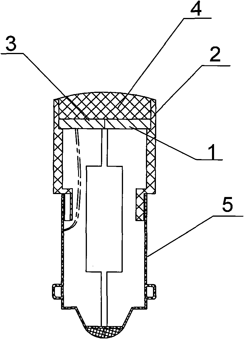
[0015] Such as figure 1 Shown, a kind of manufacturing method of LED indicator light, this method comprises the following steps:

[0016] a. Add silicon dioxide powder in the epoxy resin, the ratio is 6%, and stir evenly to increase the viscosity of the epoxy resin;

[0017] b. Put the PCB circuit board 1 with LED into the reflective cavity 3 formed by the plastic shell 2 and place it flat;

[0018] c. Use a glue filling machine to inject the prepared epoxy resin from the front of the reflection cavity 3, cover the PCB circuit board 1 with LEDs, and form an arc-shaped epoxy resin layer 4 on the front of the reflection cavity; because it is specially prepared epoxy resin glue , high viscosity, the glue will not flow out along the PCB gap to the other side of the circuit board with electronic components, all electronic components are sealed ins...


PUM


Abstract

The invention discloses a method for manufacturing an LED indicator light, which comprises the following steps: a. mixing silicon dioxide powder in epoxy resins and stirring evenly to increase the consistency of the epoxy resins; b. smoothly placing a printed circuit board (PCB) 1 with LEDs in a reflection cavity 3 formed by a plastic shell 2; c. injecting the mixed epoxy resins from the front face of the reflection cavity 3 by a glue-pouring device to cover the PCB 1 with LEDs and forming an arc epoxy resins layer 4 at the front face of the reflection cavity; and d. baking to shape. The invention reduces the manufacture procedures of the LED indicator light and enhances the reliability of the LED indicator light. All electronic elements of the invention are sealed in the LED indicator light and are not in contact with the epoxy resins, thereby avoiding that the elements are damaged to cause the failure of the LED indicator light and achieving the purpose of reducing the cost.

Description

technical field [0001] The invention relates to a method for manufacturing an LED indicator light, which belongs to the field of optoelectronic technology. Background technique [0002] LED is an energy-saving and environment-friendly light source, which is widely used in various aspects, and LED can be used to manufacture signal indicators. At present, the existing manufacturing method of the LED indicator light is as follows: adopt sealing film to closely cooperate with the reflective cavity of the indicator light, inject epoxy resin into the reflective cavity from the reverse side, vacuumize and defoam, and then place the PCB (printed circuit board) with LED Board) combined with the reflective cavity, the epoxy resin will cover the front and back sides of the PCB with LEDs, put it in an oven to bake and cure, and the product will be manufactured, and finally the sealing film will be removed. The LED indicator light manufactured in this way includes a plastic casing, a PC...

Claims


Application Information

Patent Timeline
IPC IPC(8): F21S2/00F21V7/00F21V19/00H01L33/00F21Y101/02F21K9/90F21Y115/10
Inventor 胡建红
Owner 中外合资江苏稳润光电有限公司
Learn More