
Spread spectrum clock generator

A technology of clock generator and spread spectrum clock, which is applied in the direction of reducing electrical interference, automatic power control, electrical components, etc., can solve problems such as capacitive area locking time, duty cycle, etc., and achieve the effect of solving the duty cycle problem

Inactive Publication Date: 2010-03-10
FARADAY TECH CORP
View PDF0 Cites 5 Cited by
  • Summary
  • Abstract
  • Description
  • Claims
  • Application Information

AI Technical Summary

Problems solved by technology

[0010] The present invention provides a spread spectrum clock generator to solve the capacitor area problem, lock time problem and duty cycle problem of the traditional technology

Method used


Image

  • Spread spectrum clock generator
  • Spread spectrum clock generator
  • Spread spectrum clock generator

Examples


Embodiment Construction

[0078] Image 6 It is a schematic circuit diagram of a spread spectrum clock generator 600 according to an embodiment of the present invention. The spread spectrum clock generator 600 includes a modulation module 602 and a voltage-controlled delay 601 , wherein the voltage-controlled delay 601 is coupled to the modulation module 602 . A voltage-controlled delay is a component similar to a voltage-controlled oscillator (VCO: voltage control oscillator), whose delay time can be controlled by an external voltage. The input clock signal Fin is delayed by the voltage-controlled delay unit 601 to become the output clock signal Fout, and the control voltage Vc provided by the modulation module 602 can control the delay time of the voltage-controlled oscillator 601 to the input clock signal Fin.

[0079] The change of the above delay time is the change of the clock period, that is, the change of the clock frequency. In other words, the voltage controlled delay 601 can frequency modu...


PUM


Abstract

The invention discloses a spread spectrum clock generator, which comprises a modulation module and a voltage control delayer, wherein the modulation module provides a control voltage; and the voltagecontrol delayer is coupled to the modulation module and performs frequency modulation on an input clock signal according to the control voltage so as to provide an output clock signal, wherein a modulation function of the output clock signal is a periodic function of time.

Description

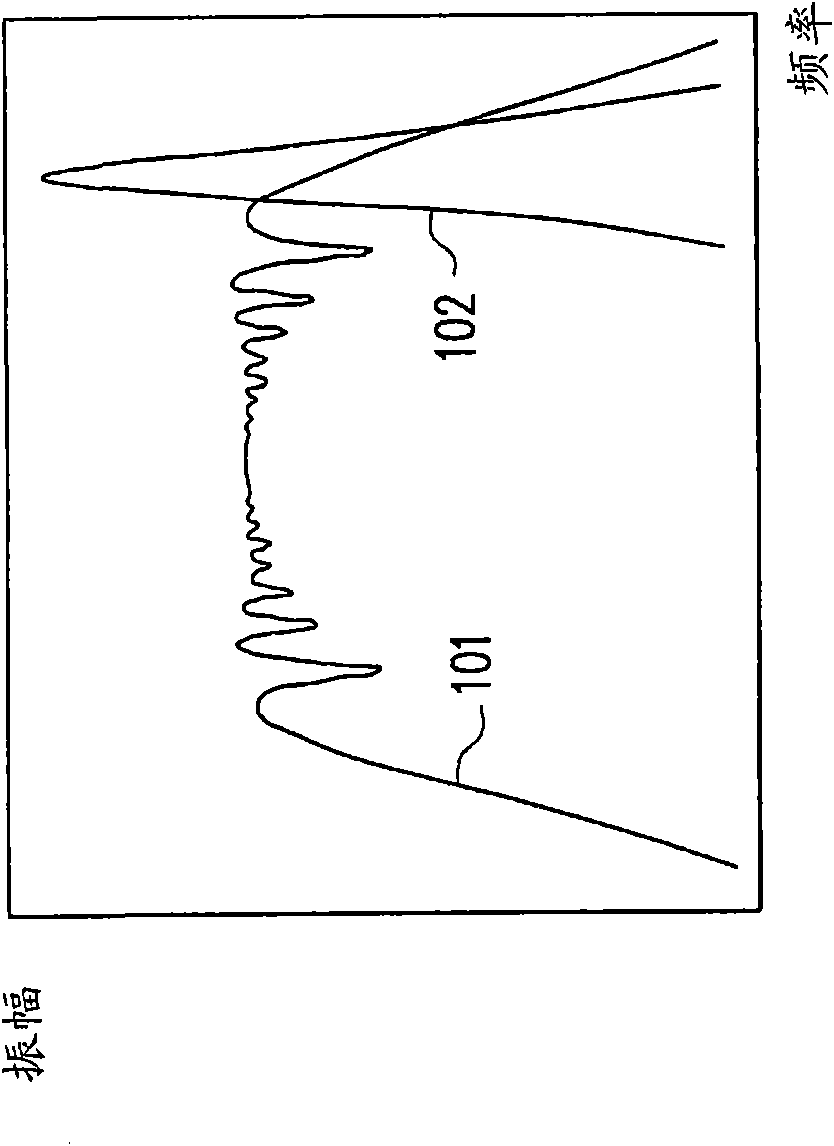
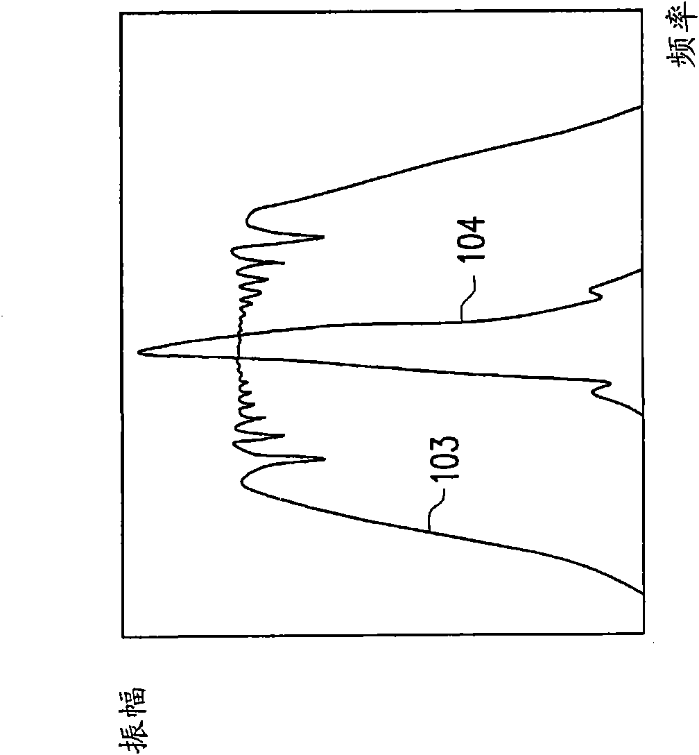
technical field [0001] The present invention relates to a spread-spectrum clock generator (SSCG: spread-spectrum clock generator), in particular to a spread-spectrum clock generator including a voltage-controlled delay (VCDL: voltage-controlled delay line). Background technique [0002] Spread spectrum (spread-spectrum) is a technique for modulating the clock frequency. The general clock signal without spread spectrum has a fixed frequency. The energy of this clock signal is concentrated in a single frequency spectrum component (tone), and the electromagnetic interference (EMI: electro-magnetic interference) is serious. However, the energy of the spread-spectrum clock signal will be dispersed into multiple spectrum components, which can reduce the amplitude of each component and reduce electromagnetic interference. Figure 1A and Figure 1B Two known spreading methods are shown. Figure 1A The down spread method is shown, that is, extending to the low frequency. The spectr...

Claims


Application Information

Patent Timeline
Patent Type & Authority Applications(China)
IPC IPC(8): H03L7/00H04B1/69H04B15/04
Inventor 韩松融
Owner FARADAY TECH CORP
Learn More