
Three-stage brushless micro gas turbine electricity generation grid-connecting device and grid connecting method

A micro, gas turbine technology, applied in the direction of single grid parallel feeding arrangement, etc., can solve the problems of slow power generation grid connection, grid shock, power system voltage drop, etc., and achieve the effect of improving power generation quality, reducing shock, and increasing speed

Inactive Publication Date: 2010-03-10
NORTHEASTERN UNIV
View PDF0 Cites 4 Cited by
  • Summary
  • Abstract
  • Description
  • Claims
  • Application Information

AI Technical Summary

Problems solved by technology

When the three-stage brushless micro gas turbine is connected to the grid for power generation, it will have an impact on the grid. When the impact is severe, it will not only cause a large drop in the voltage of the power system, but may also cause damage to the generator and mechanical components.
[0004] The existing three-stage brushless micro gas turbine power generation grid connection method and device have a large impact on the grid when power generation is connected to the grid, and the speed of power generation grid connection is slow, which affects the quality of power generation

Method used


Image

  • Three-stage brushless micro gas turbine electricity generation grid-connecting device and grid connecting method
  • Three-stage brushless micro gas turbine electricity generation grid-connecting device and grid connecting method
  • Three-stage brushless micro gas turbine electricity generation grid-connecting device and grid connecting method

Examples


Embodiment

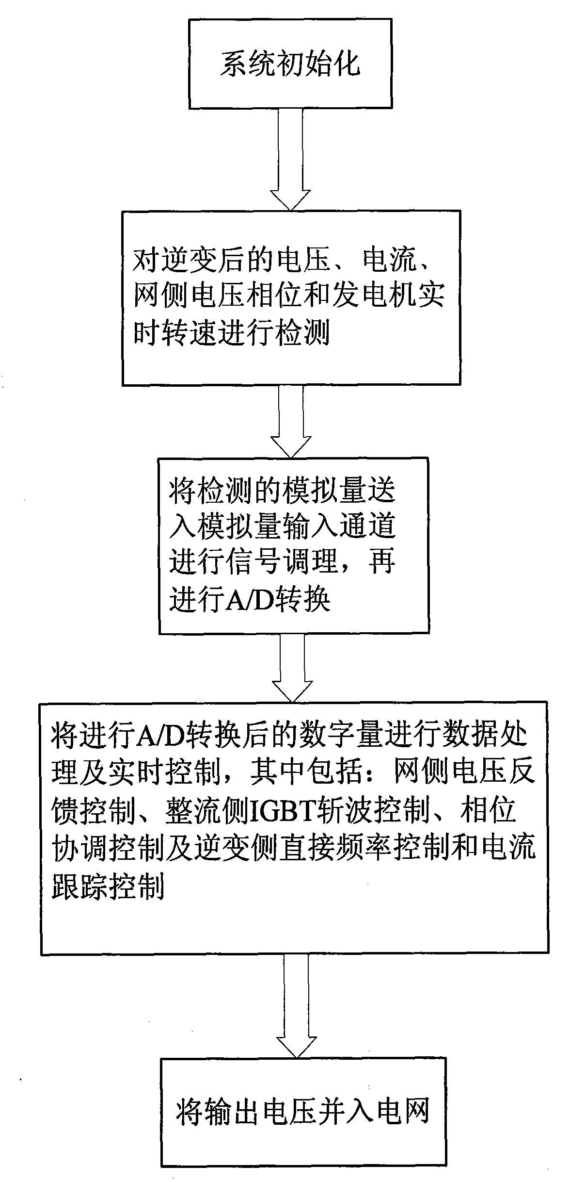
[0074] Now take the grid connection of 75KW medium frequency micro gas turbine as an example.

[0075] The 75KW medium frequency micro gas turbine is a three-phase four-wire system, but the unit does not lead out the neutral line to the load; therefore, the voltages mentioned below are all line voltages. Among them, the rated voltage is 208V, the rated power is 75KW, the maximum power is 82.5KW, the rated power factor is 0.7, and the rated frequency is 400Hz. The DC power supply uses a 27V battery.

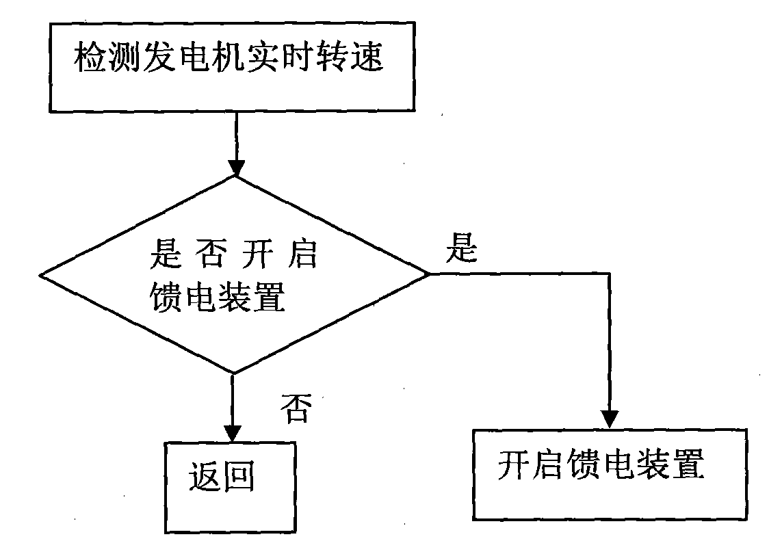
[0076] The output current feedback of the intermediate frequency micro gas turbine, the transformation ratio of the current transformer is 90:1; the output voltage feedback, the transformation ratio of the voltage measurement transformer is 17:1. In order to shorten the grid-connection time of generator power generation, appropriate electric energy is fed from the grid side through the feeder device according to the real-time speed, which improves the response speed of power gene...


PUM


Abstract

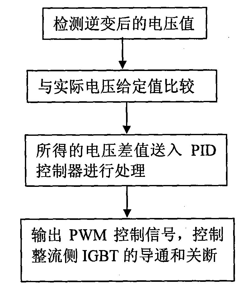
The invention relates to a three-stage brushless micro gas turbine electricity generation grid-connecting device and a grid connecting method, belonging to the technical field of gas turbine electricity generation. The invention can improve the grid connecting speed and electricity generation quality and effectively reduce the impact on an electricity grid in grid connecting. The three-stage brushless micro gas turbine electricity generation grid-connecting device comprises a microprocessor; the output end of a micro gas turbine is connected with an IGBT chopper circuit via a rectifier circuitand a filter circuit, and the IGBT chopper circuit is connected with an inverter; a PWM output interface is connected with the IGBT chopper circuit and an enabling end of the inverter via an IGBT drive circuit, and an electricity grid feed control signal is connected with an power energy input port via a feed device; a detection device is connected with an A / D conversion module via an analog input channel; a phase coordination control signal is connected with a phase coordinator; and a voltage measuring transformator is connected with a phase-locked loop frequency multiplication circuit and acapture port via a shaping circuit, and the phase-locked frequency multiplication circuit is connected with an external interrupt pin of the microprocessor. The grid connecting method adopts grid side voltage feed control, rectification side IGBT chopping control, phase coordination control, inversion side direct frequency control and current tracking control.

Description

technical field [0001] The invention belongs to the technical field of gas turbine power generation, and in particular relates to a three-stage brushless micro gas turbine power generation grid connection device and a grid connection method. Background technique [0002] With the strengthening of the concept of environmental protection and the widespread use of renewable energy, micro-gas turbine power generation technology has been increasingly valued, and micro-gas turbine power generation uses clean and renewable energy. The AC / DC / AC-based micro gas turbine power generation system has improved the operating characteristics of the power generation system and has received widespread attention from the power industry. The micro gas turbine power generation system is close to the end user, and the capacity is very small, generally tens of kilowatts to tens of megawatts. It can be used for isolated power supply or grid-connected power supply, and can be directly connected to 3...

Claims


Application Information

Patent Timeline
Patent Type & Authority Applications(China)
IPC IPC(8): H02J3/38
Inventor 杨东升张化光赵庆杞孟祥萍孙仁财孙宏彬孙秋野杨珺王迎春刘铁
Owner NORTHEASTERN UNIV
Learn More