
Method for improving magnetron-sputtered film thickness uniformity

A technology of uniform film thickness and magnetron sputtering, which can be used in sputtering coating, ion implantation coating, metal material coating process, etc. Effect

Inactive Publication Date: 2010-03-03
UNIV OF ELECTRONICS SCI & TECH OF CHINA
View PDF0 Cites 19 Cited by
  • Summary
  • Abstract
  • Description
  • Claims
  • Application Information

AI Technical Summary

Problems solved by technology

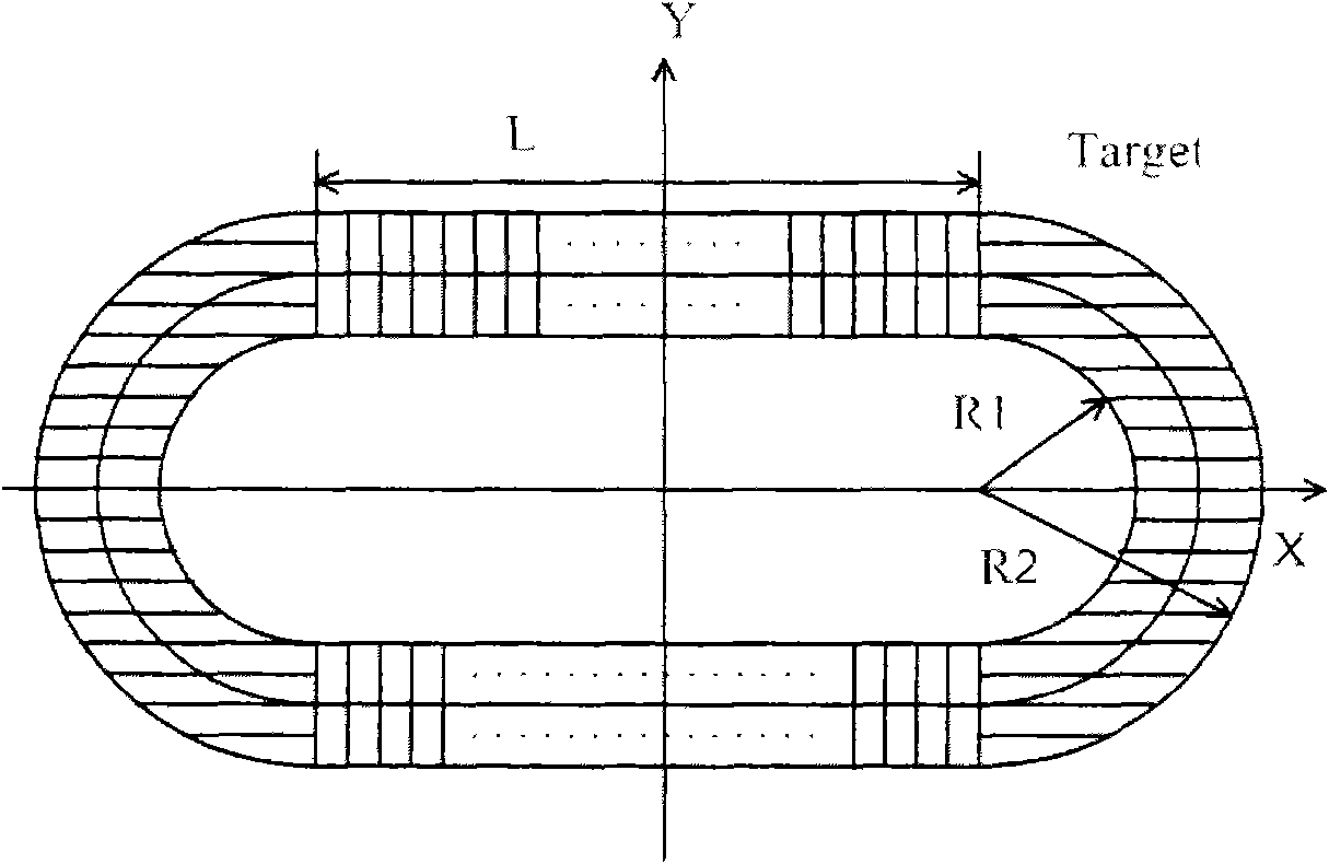
In the actual coating, sometimes the target material is not suitable for opening holes in the middle, and for the magnetron sputtering system, the target material has obvious etching runway, so the method to improve the uniformity of film thickness by changing the target shape in actual production is impossible

Method used


Image

  • Method for improving magnetron-sputtered film thickness uniformity
  • Method for improving magnetron-sputtered film thickness uniformity
  • Method for improving magnetron-sputtered film thickness uniformity

Examples


Embodiment Construction

[0037] The present invention will be further described below in conjunction with accompanying drawing:

[0038] A method of improving the thickness uniformity of the magnetron sputtering film by using a correction baffle of the present invention adopts the following steps:

[0039] Step (1) Determine the relative film thickness of the planar rectangular target magnetron sputtering system at a certain point on the plane

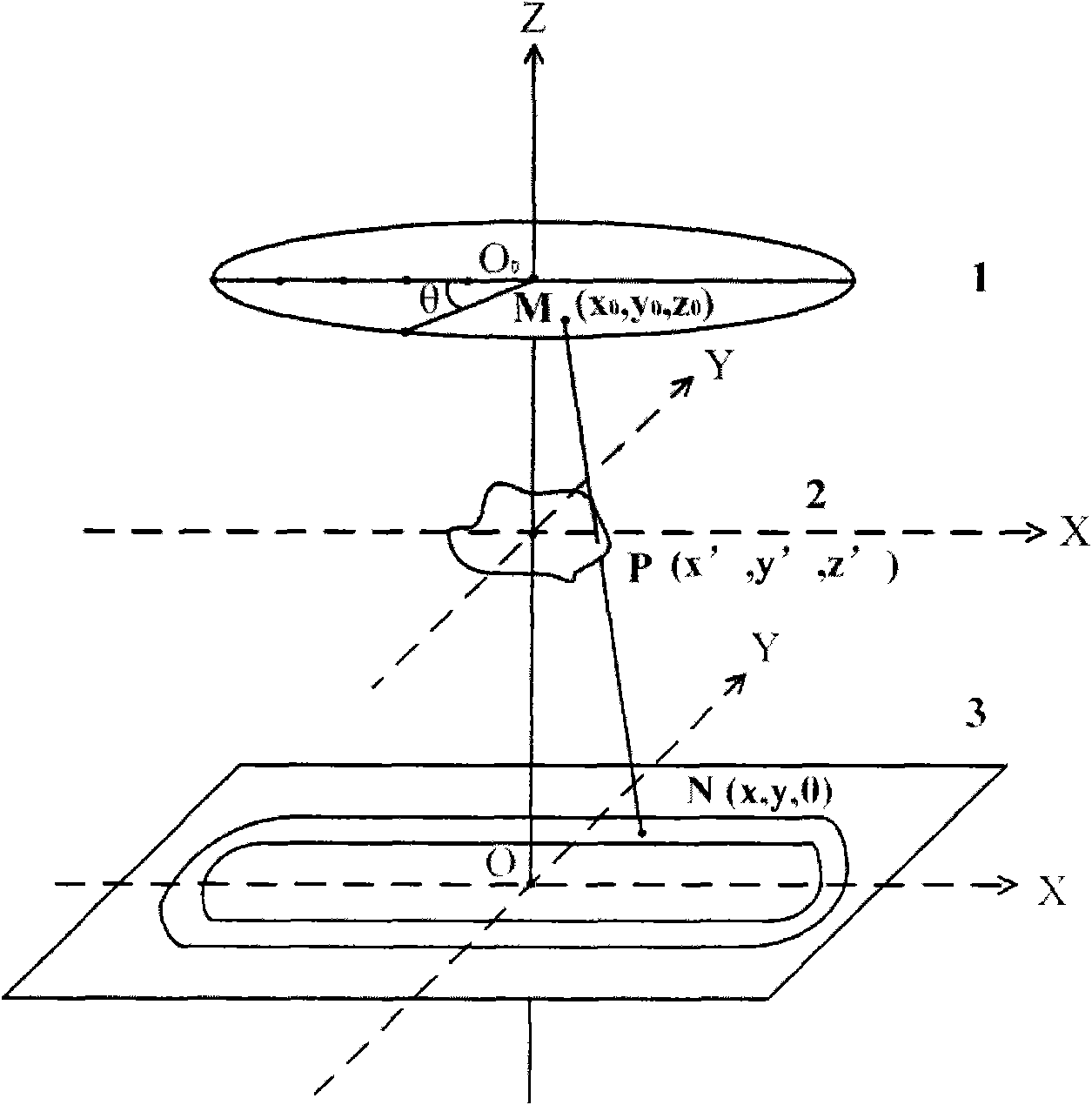
[0040] P is any point on the substrate, and its coordinates are (x', y'). ds is the tiny bin of point P. Q is a point in the sputtering runway area, its coordinates are (x, y), and dσ is the tiny facet of point Q. In unit time, the thickness of the thin film deposited on ds by the small bin can be expressed by the formula [9] Expressed as

[0041] t = m cos θ cos β πρ r 2 ...


PUM


Abstract

The invention discloses a method for improving magnetron-sputtered film thickness uniformity. An optimum correcting baffle is arranged between two planes of a substrate and a target. The centers of the substrate, the target and the correcting baffle are coaxial. A baffle theory model relatively close to actual situation is created, and baffle parameters for realizing optimum film thickness uniformity are calculated. The method reduces the deposition rate of a position close to the circle center on the substrate to a certain extent, thereby optimizing and improving the uniformity.

Description

technical field [0001] The invention relates to the technical field of electromechanics, in particular to a method for improving the uniformity of magnetron sputtering film thickness. Background technique [0002] Among the various sputtering coating technologies, magnetron sputtering technology is one of the most important technologies. In order to prepare large-area uniform films with consistent batches, a large number of researchers have optimized the target base distance, changed the movement mode of the substrate, Implement film thickness monitoring and other measures. Multi-station magnetron sputtering coating equipment has been paid more and more attention to and used because of its adjustable speed ratio and the simultaneous production of multiple substrates, which greatly improves the efficiency. [0003] In order to achieve the purpose of preparing a large-area uniform film, the X.Q.Meng research group theoretically derived the film thickness distribution formula ...

Claims


Application Information

Patent Timeline
IPC IPC(8): C23C14/54C23C14/35
Inventor 王涛陈超于贺吴志明蒋亚东
Owner UNIV OF ELECTRONICS SCI & TECH OF CHINA
Learn More