
Low rudder supporting axle processed tooling

A technology for supporting shafts and tooling, which is used in supports, metal processing equipment, metal processing machinery parts, etc., and can solve problems such as high technical requirements, inability to guarantee product quality stability, and difficulty in guaranteeing shape and position tolerances.

Inactive Publication Date: 2010-03-03
南通德玛瑞机械制造有限公司
View PDF0 Cites 9 Cited by
  • Summary
  • Abstract
  • Description
  • Claims
  • Application Information

AI Technical Summary

Problems solved by technology

The traditional machining of the lower rudder support shaft uses a four-claw fixture to process the end face of the cylindrical shaft, and then mills the bottom surface and groove of the support seat on a boring machine. The technical requirements are high, the shape and position tolerances are difficult to guarantee, and the stability of product quality cannot be guaranteed.

Method used


Image

  • Low rudder supporting axle processed tooling
  • Low rudder supporting axle processed tooling
  • Low rudder supporting axle processed tooling

Examples


Embodiment Construction

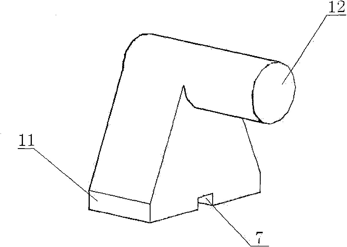
[0009] Such as figure 1 As shown, the lower rudder support shaft is integrally formed by a support base 11 and a cylindrical shaft 12, the cylindrical shaft 12 is horizontally arranged on the support base 11, and the bottom surface of the support base 11 is provided with a right angle groove 7 parallel to the axis of the cylindrical shaft 12.

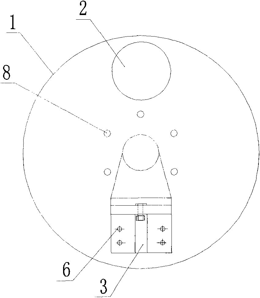
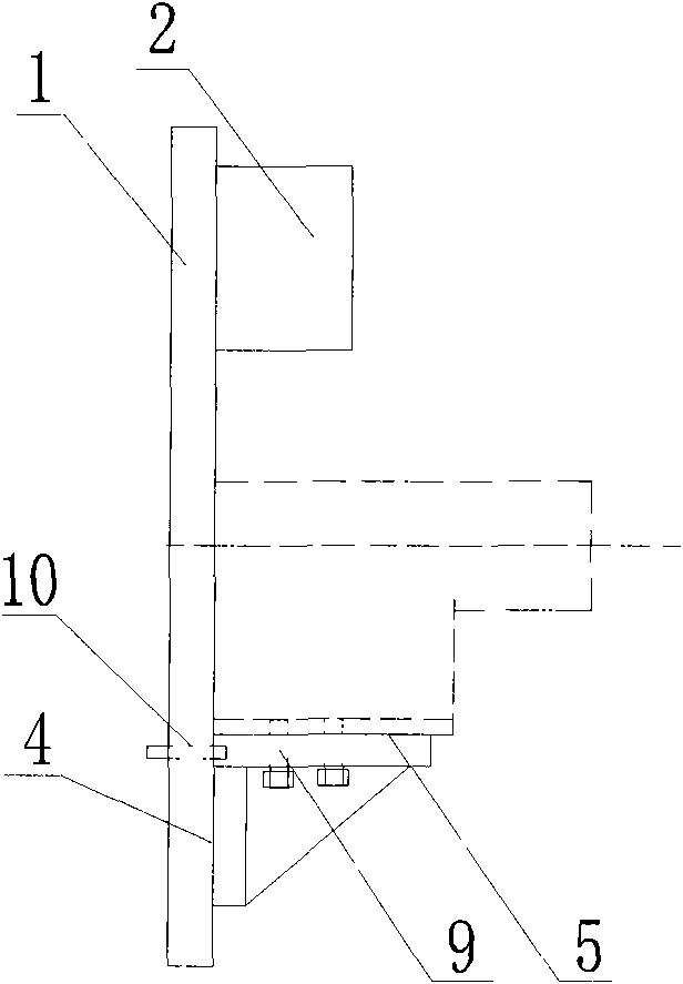
[0010] Such as figure 2 , 3 As shown, the present invention relates to a processing tool for the lower rudder support shaft, which includes a faceplate 1, a hole 8, an angle iron 3, and a counterweight 2.

[0011] The above-mentioned faceplate 1 is provided with a hole 8 for fixing the faceplate on the main shaft of the lathe, and an angle iron 3 is arranged at the bottom. The angle iron 3 has two mutually perpendicular right-angled surfaces 4, 5, the right-angled surface 4 is fixed on the faceplate 1 by bolts 6, and its central symmetry line passes through the center of the faceplate 1, and the right-angled surface 4 is provided wit...


PUM


Abstract

The invention relates to a low rudder supporting axle processed tooling and the main body of the processed tooling is a face plate provided with a central hole at the center thereof. The innovation points lie in: the upper part of the face plate is connected with a counterweight block, and the lower part thereof is provided with an angle iron; the angle iron is provided with two mutually-perpendicular right-angle planes, a first right-angle plane is connected with the face plate, and the other one is arranged at one side close to the central hole of the face plate and is provided with an installation hole and a positioning hole; and the positioning hole is internally connected with a positioning pin. The invention has the advantages that a base of the lower rudder supporting axle is fixedon the right-angle plane in which the angle iron faces the central hole of the face plate after being processed into a right-angle groove, the positioning pin is used for extending into the groove ofthe lower rudder supporting axle to position the bottom surface thereof and the groove, thus determining processing standard of the cylinder axis end surface of the lower rudder supporting axle and ensuring geometric tolerance among the cylinder axis, the bottom surface and the groove.

Description

technical field [0001] The invention relates to a processing tool for a lower rudder support shaft, the main body of which is a faceplate with a central hole in the center. Background technique [0002] The lower rudder support shaft is used for the support of the lower rudder of the ship, and consists of a support seat and a horizontally arranged cylindrical shaft. The bottom surface of the support seat is provided with a right-angled groove parallel to the axis of the cylindrical shaft. It has high requirements on the parallelism between the bottom surface and the end surface of the cylinder shaft and the central symmetry between the bottom surface groove and the end surface of the cylinder shaft during processing. The traditional machining of the lower rudder support shaft uses a four-jaw fixture to process the end face of the cylindrical shaft, and then mills the bottom surface and groove of the support seat on a boring machine. The technical requirements are high, the s...

Claims


Application Information

Patent Timeline
IPC IPC(8): B23Q3/12
Inventor 沈辉姜兵赵永柏
Owner 南通德玛瑞机械制造有限公司
Learn More