Automatic welding method of electrically heated element bushing of voltage stabilizer and reducing bushing of electrically heated element bushing

A technology of electric heating element and transition sleeve, which is applied in welding equipment, arc welding equipment, metal processing equipment, etc., can solve the problems of large deformation of electric heating element sleeve, dead angle, and time-consuming correction, etc., so as to reduce the difficulty of operation. and labor intensity, reducing the correction of post-weld deformation, and improving the first pass rate

Inactive Publication Date: 2010-02-24
SHANGHAI ELECTRIC POWER GENERATION EQUIPMENT CO LTD
View PDF0 Cites 5 Cited by
  • Summary
  • Abstract
  • Description
  • Claims
  • Application Information

AI Technical Summary

Problems solved by technology

In the past, the weld was welded by manual wire tungsten argon arc welding. The direct weaknesses reflected in the welding process are: first, the tight mutual position between the electric heating element sleeves makes the welding of the weld have a certain blind area, that is, Welding with obstacles and dead angles invisible to the welder
Second, the accessibility of the welding torch is not good, which affects the performance of the welder's operation skills, and there is a certain amount of rework
If it is repaired, it is very likely to cause the expensive electric heating element sleeve to be scrapped, which will greatly increase the manufacturing cost of the product
Third, the large deformation of the electric heating element casing after welding will take a lot of time to correct, and it may be scrapped again
[0003] Due to the particularity of the casing structure of the electric heating element in this product, professional welding equipment factories at home and abroad have no automatic welding process for this type of pipe butt joint.

Method used


Image

  • Automatic welding method of electrically heated element bushing of voltage stabilizer and reducing bushing of electrically heated element bushing
  • Automatic welding method of electrically heated element bushing of voltage stabilizer and reducing bushing of electrically heated element bushing
  • Automatic welding method of electrically heated element bushing of voltage stabilizer and reducing bushing of electrically heated element bushing

Examples


Embodiment 1

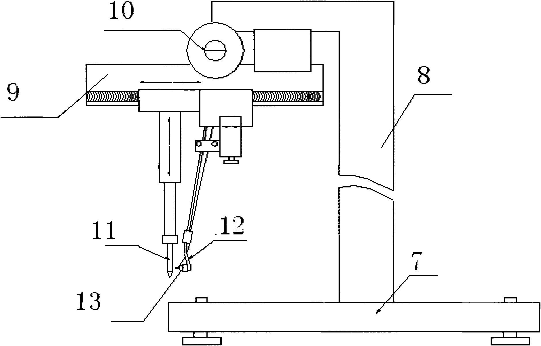
[0019] The welding torch used in the welding method in the present embodiment is as figure 2 Shown, comprise gantry 7, be provided with support 8 vertically on gantry 7, be provided with wire feeding device 10 and the rotating track 9 perpendicular with support 8 on the top of support 8, be provided with center vertically on rotating track 9 The rod 11 and the welding torch base 12 with the wire feed rod are provided with a tungsten electrode 13 at the end of the welding torch base 12 .

[0020] combine figure 1 and figure 2 , the specific steps of the automatic welding welding method of the voltage stabilizer electric heating element bushing and its transition bushing of the present embodiment are:

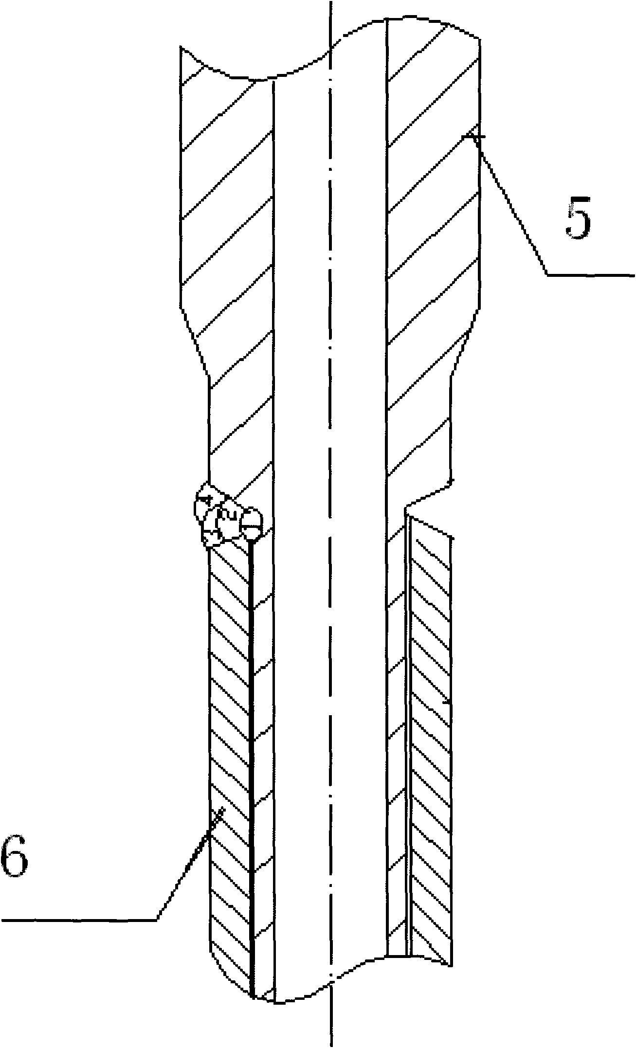
[0021] Step 1. Insert the tungsten electrode of the welding torch into the groove between the electric heating element sleeve 5 of the voltage regulator and the transition sleeve 6 and point to the root of the groove, adjust the position of the welding torch so that the axis ...

Embodiment 2

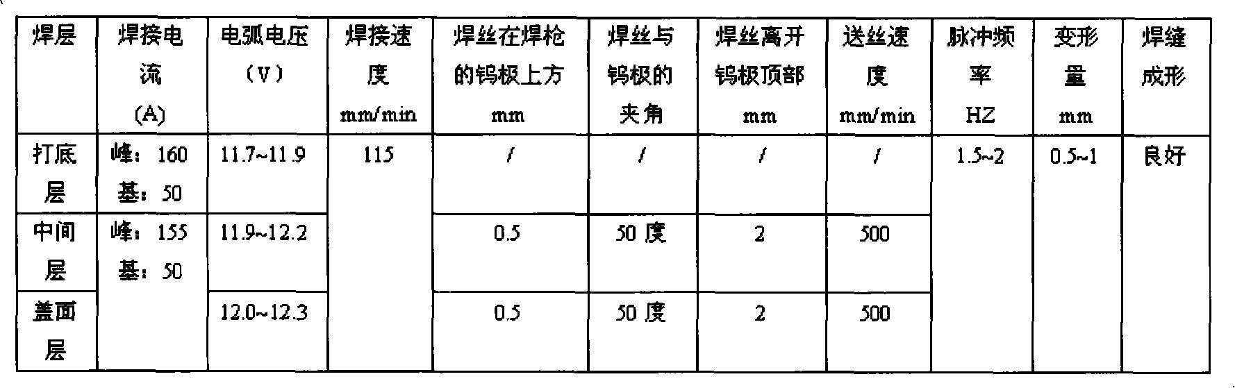
[0027] The steps of this embodiment are the same as those of Embodiment 1, except that the parameters used are different, as shown in the following table:

[0028]

Embodiment 3

[0030] The steps of this embodiment are the same as those of Embodiment 1, except that the parameters used are different, as shown in the following table:

[0031]


PUM


Abstract

The invention relates to an automatic welding method of an electrically heated element bushing of a voltage stabilizer and a reducing bushing of the electrically heated element bushing, which is characterized by comprising the following steps: firstly, carrying out non-wire feeding melting welding on a beveling root between the electrically heated element bushing of the voltage stabilizer and thereducing bushing of the electrically heated element bushing by adopting automatic impulse argon-arc welding, wherein, a welding gun takes an axes of the reducing bushing as a center line to rotates 360 DEG to finish welding so as to form a first root base coat in the welding process; and then finishing a second middle wire feeding welding layer, a third cosmetic wire feeding welding layer and a fourth cosmetic wire feeding welding layer by automatic impulse synchronous wire feeding argon-arc welding. The invention has the advantages of realizing automatic impulse argon-arc welding barrier-freespin welding used for the electrically heated element bushing with more amount, complex arrangement and welding blind area existence and the reducing bushing thereof, improving the primary welding qualification rate, controlling the welding deformation by selecting a reasonable parameter of an automatic welding process, lowering the operation difficulty and the labor intensity of welders, reducing the correction of deformation after welding, and improving the production efficiency.

Description

technical field [0001] The invention relates to an automatic welding method for electric heating element sleeves and transition sleeves of a voltage stabilizer, in particular to an automatic welding process for electric heating element sleeves with a large number and complex arrangement and their transition sleeves, which can be used for electric heating of voltage stabilizers The welding of component sleeves, transition sleeves and other similar nuclear power products belongs to the technical field of welding methods. Background technique [0002] The number of small-diameter butt welds between the electric heating element sleeve and the transition sleeve is large and the arrangement is compact, and the minimum distance between the threaded heads of the electric heating element sleeve is 30mm. In the past, the weld was welded by manual wire tungsten argon arc welding. The direct weaknesses reflected in the welding process are: first, the tight mutual position between the el...

Claims


Application Information

Patent Timeline
Patent Type & Authority Applications(China)
IPC IPC(8): B23K9/167B23K9/028B23K9/095
Inventor 陈龙鹤王晖许庆和
Owner SHANGHAI ELECTRIC POWER GENERATION EQUIPMENT CO LTD
Why Eureka
Try Eureka