
Stamping die for forming punching scrap and peripheral flanging simultaneously

A stamping die and flanging technology, used in forming tools, manufacturing tools, metal processing equipment, etc., can solve the problems of inability to achieve simultaneous forming, low raw material utilization, and low parts manufacturing accuracy, and achieve high material utilization, The effect of improving market competitiveness and improving product accuracy

Active Publication Date: 2010-02-24
LEMTECH PRECISION MATERIAL (CHINA) CO LTD
View PDF0 Cites 26 Cited by
  • Summary
  • Abstract
  • Description
  • Claims
  • Application Information

AI Technical Summary

Problems solved by technology

[0002] At present, some stamping products on the market, especially some parts with all sides flanging, are mainly completed by single-process molds through blanking, punching, flanging and other processes. After all the processes other than the edge are completed, and then the flanging process is realized through a single-process mold, it is impossible to realize the synchronous forming of the punching edge and the surrounding bending in the progressive die, so stamping a part requires several processes plus It can only be completed together, which makes the utilization rate of raw materials low, the manufacturing precision of parts is low, the size is unstable, the scrap rate is high, and the production efficiency is very low. At the same time, it requires a large number of personnel, stamping equipment, semi-finished turnover boxes, venues, etc.

Method used


Image

  • Stamping die for forming punching scrap and peripheral flanging simultaneously
  • Stamping die for forming punching scrap and peripheral flanging simultaneously
  • Stamping die for forming punching scrap and peripheral flanging simultaneously

Examples


specific Embodiment approach

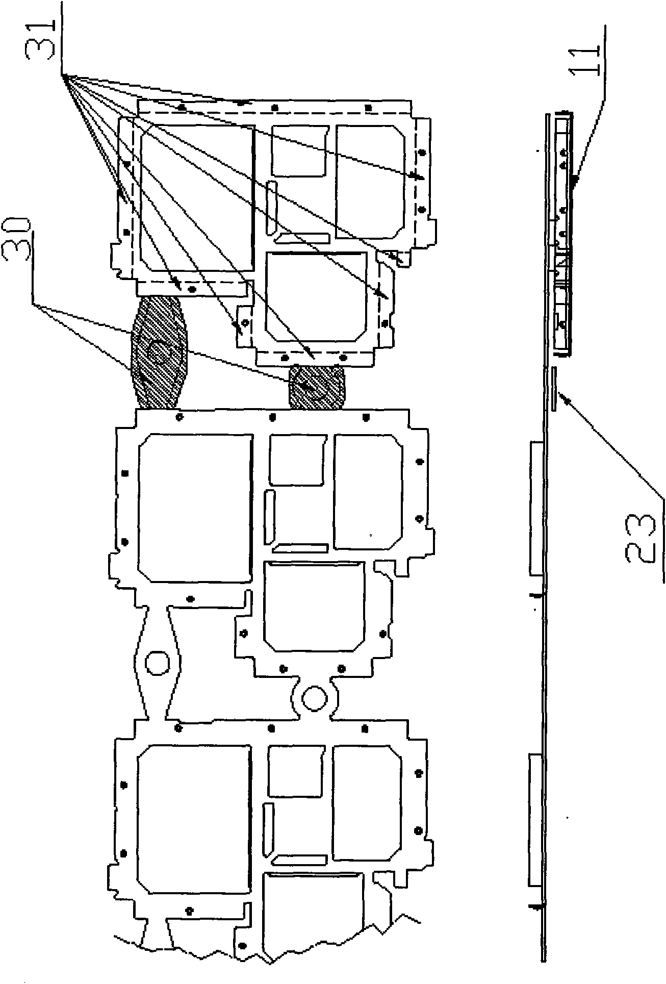
[0030] figure 1 It is a part layout drawing of the production product described in the present invention.

[0031] Such as figure 1 As shown: the edge material 30 in the shaded part needs to be punched off, and the cut part is still a semi-finished product, and part of the material of the semi-finished product 31 still needs to be bent upwards along the dotted line to become a finished product. These two steps are completed at the same time .

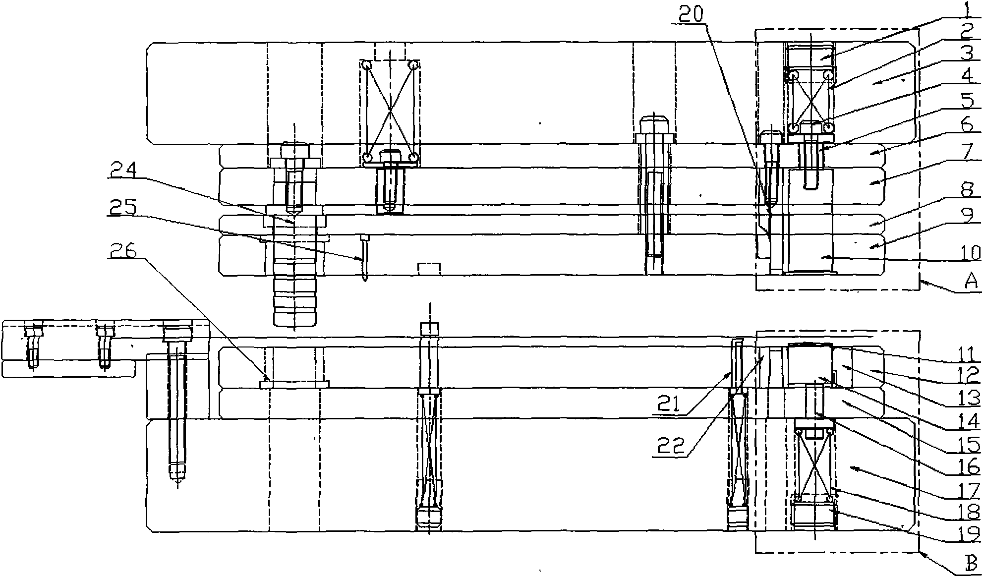
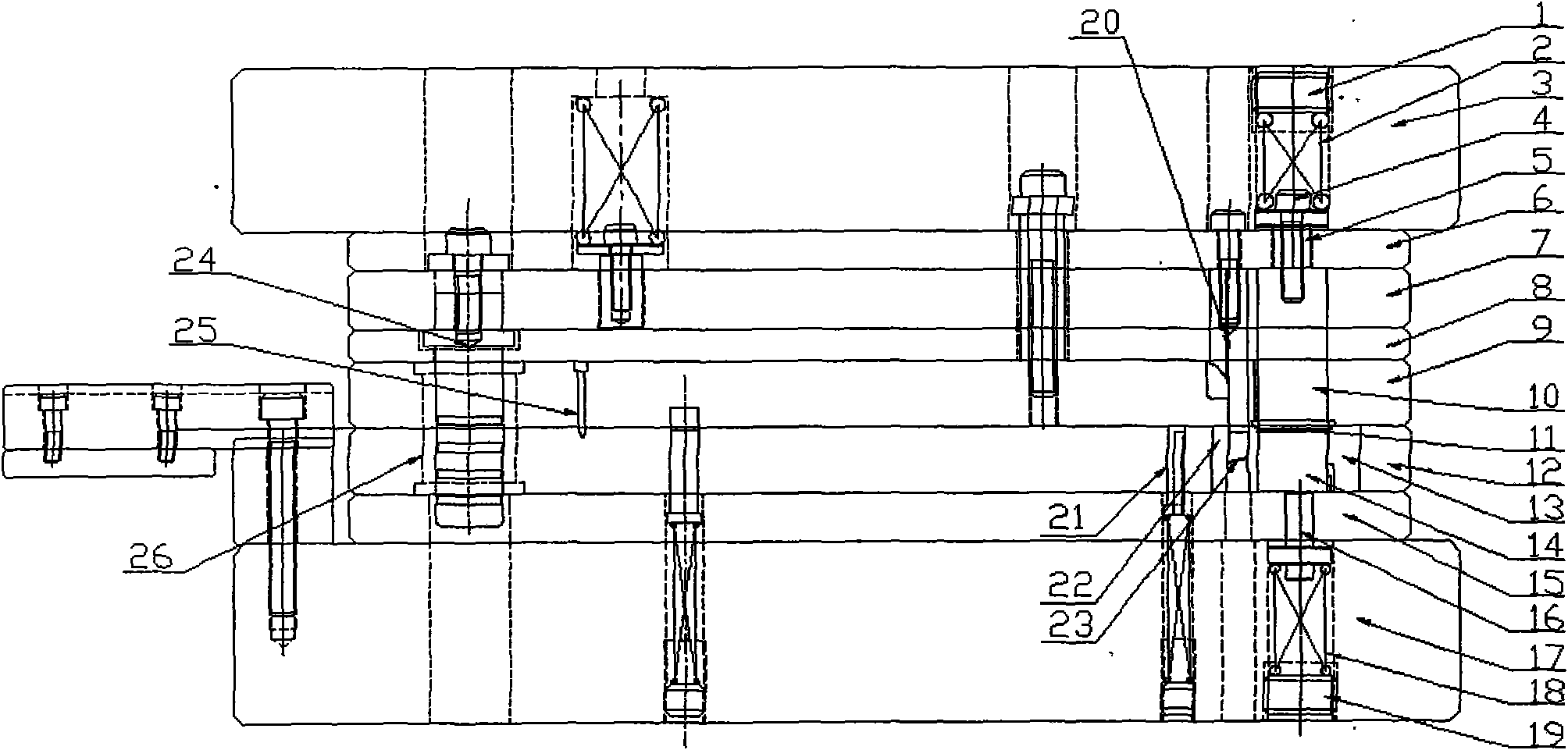
[0032] figure 2 It is an opening state diagram of an embodiment of the present invention; image 3 It is a closed state diagram of an embodiment of the present invention; Figure 4 for figure 2 Enlarged view of Part A of ; Figure 5 for figure 2 Enlarged view of Part B.

[0033] Such as Figure 2 to Figure 5 Shown: a stamping die for synchronous forming of the punching edge and the surrounding flanging, including an upper die and a lower die, wherein the upper die includes an upper die base 3, an upper backing plate 6, a pun...


PUM


Abstract

The invention discloses a stamping die for forming a punching scrap and a peripheral flanging simultaneously. The stamping die comprises an upper die and a lower die which are guided and fixed throughan inner guide pillar arranged on the upper die and an inner guide sleeve arranged on the lower die, wherein the upper die is provided with a punching terrace die and a bending terrace die; the punching terrace die is fixed on a terrace die fixed plate through an upper die screw; the bending terrace die is a movable member and is located in the terrace die fixed plate; the lower die is provided with a bending female die and a punching female die; and the punching terrace die and the bending terrace die of the upper die respectively correspond to the punching female die and the bending femaledie of the lower die. The invention reduces the procedure, personnel, stamping devices, containers of semi-finished products, sites and the like so that the use ratio of materials is higher. At the same time, the invention realizes the automatic production, increases the efficiency by nearly seven times, thereby improving the labor efficiency and the precision of products, reducing the unit priceof parts and improving the market competitiveness of products.

Description

technical field [0001] The invention relates to a stamping die, in particular to a stamping die which realizes synchronous forming of punching laps and surrounding flanging in a progressive die. Background technique [0002] At present, some stamping products on the market, especially some parts with all sides flanging, are mainly completed by single-process molds through blanking, punching, flanging and other processes. After all the processes other than the edge are completed, and then the flanging process is realized through a single-process mold, it is impossible to realize the synchronous forming of the punching edge and the surrounding bending in the progressive die, so stamping a part requires several processes plus It can only be completed together, which makes the utilization rate of raw materials low, the manufacturing precision of parts is low, the size is unstable, the scrap rate is high, and the production efficiency is very low. At the same time, a large number...

Claims


Application Information

Patent Timeline
Patent Type & Authority Applications(China)
IPC IPC(8): B21D22/06B21D37/10
Inventor 张亮
Owner LEMTECH PRECISION MATERIAL (CHINA) CO LTD
Learn More