
Fan blade frame and fan blade manufactured by same

A frame and blade technology, applied in the field of wind blades, can solve the problems of wind blades not being able to absorb more wind energy, low working efficiency of wind blades, low energy utilization rate, etc., to achieve high wind energy utilization rate, cost reduction, and contact surface many effects

Inactive Publication Date: 2010-02-17
蒋连君
View PDF0 Cites 2 Cited by
  • Summary
  • Abstract
  • Description
  • Claims
  • Application Information

AI Technical Summary

Problems solved by technology

[0002] Wind power generation is a green energy source that is non-polluting, renewable and reusable. It is one of the environmentally friendly energy sources advocated in the world today. As a component in wind power equipment that is in direct contact with natural wind, wind blades have a direct impact on the absorption of wind energy. How much wind energy is converted into electrical energy, the current wind power generation equipment can only convert a small part of wind energy into electrical energy, and the energy utilization rate is low. The main reason is that the wind blades cannot absorb wind energy more. Most of the leaves are in the shape of thick long airfoils, and the single rod is connected to the rotating shaft. The windward side of its cross section is convex arc shape. Under the action of wind, the windward side itself will generate two opposite rotational forces. Moreover, the air resistance of the fan blade is also relatively large during the rotation process, which makes the working efficiency of the fan blade low, and the stability of the connection between the single rod and the rotating shaft is also poor during the working process. Not only that, because most of the fan blades are now integral structure, it is extremely inconvenient to carry when used on large wind power equipment

Method used


Image

  • Fan blade frame and fan blade manufactured by same
  • Fan blade frame and fan blade manufactured by same
  • Fan blade frame and fan blade manufactured by same

Examples


Embodiment Construction

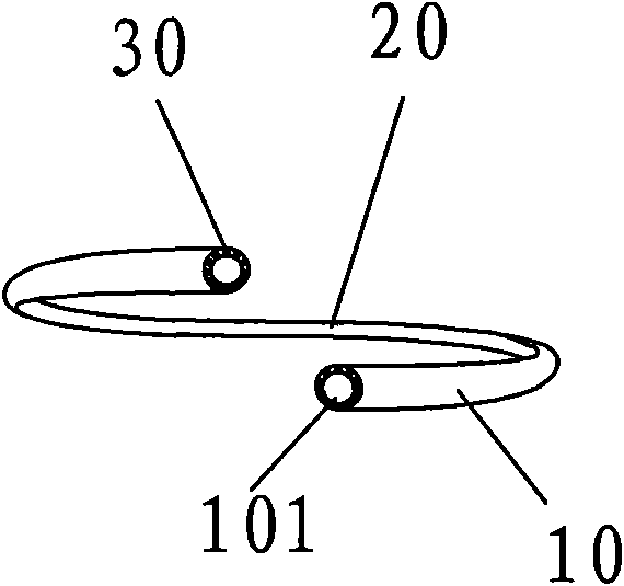
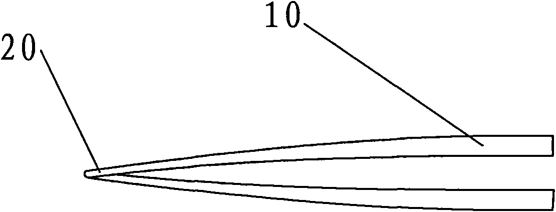
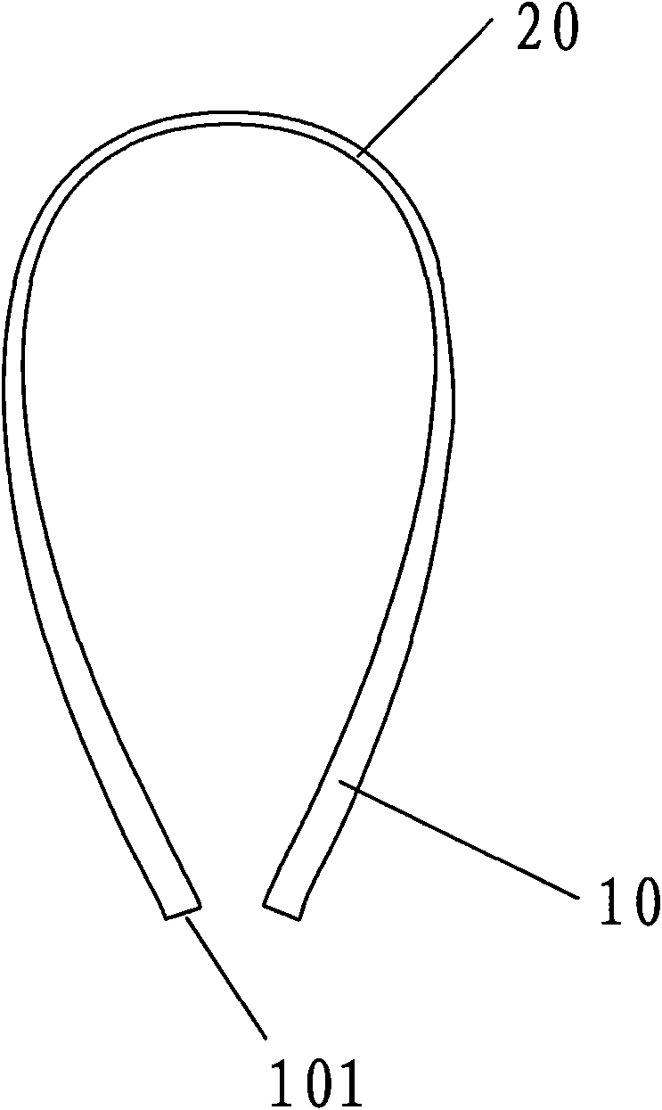
[0026] The present invention will be further described below with specific embodiments in conjunction with the drawings, see Figure 1-9 :

[0027] Fan blade frame. The frame includes a support rod 10 and a cross beam 20. The central axis of the frame has a through hole. The support rod 10 is a unequal-diameter arc structure and has a rotating shaft connecting end 101 to the middle outer diameter of the cross beam 20. With the wall thickness gradually reduced, the ratio of the outer diameter of the end surface of the connecting end 101 of the support rod 10 and the rotating shaft to the middle part of the beam 20 is 10:1, and the ratio of the wall thickness is 4:1. The beam 20 is U-shaped arc body, the end surface of the shaft connecting end 101 of the support rod 10 is provided with a plurality of connecting holes 30 fixedly connected with the shaft, the support rod 10 of the frame is twisted up and down to form a frame with a twisted shape, and the through hole is provided with...


PUM


Abstract

The invention belongs to the technical field of wind power generation, and relates to a fan blade manufactured by using a fan blade frame. The frame comprises supporting rods and a beam, and a middleshaft of the frame is provided with a through hole, wherein the supporting rod is in a waney arc structure, a rotation shaft connecting end of the arc structure is connected to the middle part of thebeam, and the outer diameter and the wall thickness of each supporting rod are gradually reduced. The beam is a U-shaped arc, and the end face of a rotation shaft connecting end of each supporting rodis provided with a plurality of connection holes which are fixedly connected with a plurality of rotation shafts. The upper parts and the lower parts of the supporting rods of the frame are twisted to form a twisted frame. The invention has the advantages of more contact surfaces with natural wind, high wind energy utilization rate, good stability due to the double-rod connection with the rotation shafts, length reduction compared with other fan blades with the same power and great cost reduction. The fan blade frame is of a detachable type and can be transported detachably when required to be transported, thus the fan blade frame is convenient to transport.

Description

Technical field [0001] The invention belongs to the technical field of wind power generation, and particularly refers to a wind blade frame and a wind blade made of the wind blade frame. Background technique [0002] Wind power is a pollution-free, renewable and reusable green energy source. It is one of the environmentally friendly energy sources advocated in the world today. As a part of wind equipment that directly contacts with natural wind, wind blades directly affect the absorption of wind energy. How much wind energy is used and converted into electric energy. In current wind power equipment, only a small part of wind energy can be converted into electric energy. The energy utilization rate is low. The main reason is that the wind blades cannot absorb more wind energy. The blades are mostly thick and long stream wing-shaped, and the single rod is connected with the rotating shaft. The windward side of its cross section is convex arc. Under the action of wind, the windward ...

Claims


Application Information

Patent Timeline
Patent Type & Authority Applications(China)
IPC IPC(8): F03D1/06
CPCY02E10/72Y02E10/721Y02P70/50
Inventor 蒋连君
Owner 蒋连君
Learn More