
Large diameter steel bar connecting sleeve

A technology of connecting sleeves and connecting sleeves for steel bars, which is applied in the direction of structural elements, building components, building reinforcements, etc., can solve the problems of wasting resources, affecting the next process, and directly processing progress, so as to save construction site land and reduce equipment The effect of investment and product quality stability

Inactive Publication Date: 2010-02-17
魏勇
View PDF0 Cites 9 Cited by
  • Summary
  • Abstract
  • Description
  • Claims
  • Application Information

AI Technical Summary

Problems solved by technology

[0002] At present, there are several types of steel bar mechanical connection (thick diameter) technology in my country's construction, such as steel bar sleeve extrusion connection, steel bar taper thread sleeve connection, steel bar upsetting straight thread sleeve connection, steel bar rolling straight thread sleeve connection, etc. Compared with welding connection, the mechanical connection of steel bars not only saves a lot of steel, but also saves auxiliary materials such as electric energy and solder. However, the above-mentioned types of mechanical connection processes have common shortcomings, that is, special steel processing equipment is required. , and need to occupy limited construction site land, need to be equipped with a certain number of operators for processing, and because the processing quality is not stable, it is also necessary to be equipped with special quality inspection personnel for inspection. At the same time, the processing progress of steel bars directly affects the next process. It even affects the construction progress of the entire project, not only wastes resources, but also the quality and progress of the construction cannot be well guaranteed

Method used


Image

  • Large diameter steel bar connecting sleeve
  • Large diameter steel bar connecting sleeve
  • Large diameter steel bar connecting sleeve

Examples


Embodiment Construction

[0019] The present invention will be further described below in conjunction with the accompanying drawings.

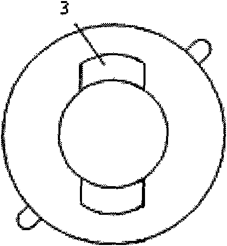
[0020] Depend on Figure 1-10 It can be seen that when connecting the thick-diameter steel bars 5 (above Φ16) coaxially, the two ends of the two steel bars 5 to be connected are respectively penetrated into the fastening sleeve 4, and then inserted into the connecting sleeve 1 , the end of the steel bar 5 is located about 10mm from the center line of the connecting sleeve 1, and then the tapered clip 2 is inserted into the tapered groove 3, and then the fastening sleeve 4 is initially screwed onto the connecting sleeve 1, so that The steel bar will not slide. Finally, use a special torque wrench to screw the fastening sleeve 4 to the specified final torque value. During the tightening process of the fastening sleeve 4, the tapered clip 2 is tightened along the tapered groove 3. Continuously advancing, the fine teeth on the clip are continuously pressed into the steel ...


PUM


Abstract

The invention relates to a steel bar mechanical connection process in building construction, particularly to a large diameter steel bar connecting sleeve. The large diameter steel bar connecting sleeve comprises a connecting sleeve, a clamping piece and a fastening sleeve and is characterized in that the clamping piece is positioned at the internal side of the connecting sleeve; the fastening sleeve is positioned at the external side of the connecting sleeve; and the clamping piece and the connecting sleeve are wrapped inside the fastening sleeve. The large diameter steel bar connecting sleevecan connect two large diameter steel bars (above 16 diameters) coaxially and firmly and effectively bear and transfer the axial tension or the axial pressure of the two steel bars. In the case of thesteel bar mechanical connection process adopted at present, the invention can effectively reduce the equipment investment and save the occupied construction site and the labor force. Because the specialization and the social division of labor of product production are realized, the quality of products is reliable, working procedures are simple and rapid, and the construction progress can be accelerated.

Description

Technical field: [0001] The invention relates to a steel bar mechanical connection process in building construction, and relates to a large-diameter steel bar connection sleeve. technical background: [0002] At present, there are several types of steel bar mechanical connection (thick diameter) technology in my country's construction, such as steel bar sleeve extrusion connection, steel bar taper thread sleeve connection, steel bar upsetting straight thread sleeve connection, steel bar rolling straight thread sleeve connection, etc. Compared with welding connection, the mechanical connection of steel bars not only saves a lot of steel, but also saves auxiliary materials such as electric energy and solder. However, the above-mentioned types of mechanical connection processes have common shortcomings, that is, special steel processing equipment is required. , and need to occupy limited construction site land, need to be equipped with a certain number of operators for processing...

Claims


Application Information

Patent Timeline
Patent Type & Authority Applications(China)
IPC IPC(8): E04C5/16E04C5/18
Inventor 魏勇
Owner 魏勇
Learn More