Radiating and anti-carbon powder device of collector ring component of wound rotor motor
What is Al technical title?
Al technical title is built by PatSnap Al team. It summarizes the technical point description of the patent document.
A winding rotor motor, collector ring technology, applied in electromechanical devices, electric components, electrical components, etc., can solve the problems of collector ring heating, toner short circuit, etc., to extend service life, solve short circuit problems, increase sealing effect of structure
Inactive Publication Date: 2011-07-20
SIMENS SPECIAL ELECTRICAL MACHINES
View PDF0 Cites 0 Cited by
Summary
Abstract
Description
Claims
Application Information
AI Technical Summary
This helps you quickly interpret patents by identifying the three key elements:
Problems solved by technology
Method used
Benefits of technology
Problems solved by technology
[0003] The heat dissipation and carbon dust prevention device of the collector ring assembly of the wound rotor motor of the present invention solves the short circuit problem caused by the collector ring heating and carbon powder
Method used
Image
Click on the blue label to locate the original text in one second.
Reading with bidirectional positioning of images and text.
Examples
Embodiment Construction
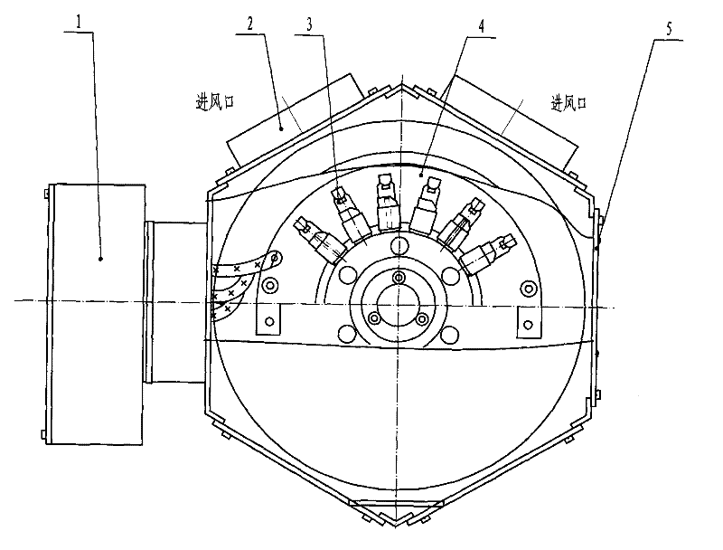
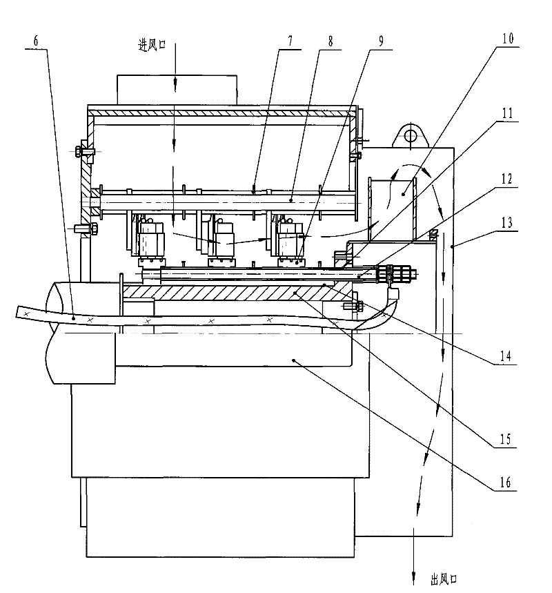
[0008] The invention provides a collector ring device for a wound rotor motor. The heat dissipation and carbon dust prevention device for the collector ring assembly of the wound rotor motor according to the invention increases the number of brushes and improves the ventilation structure on the basis of the original collector ring assembly. The sealing structure of the terminal is added to solve the short circuit problem caused by the heat of the collector ring and the carbon powder.
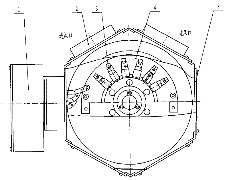
[0009] The collector ring heat dissipation and carbon dust prevention device of the wound rotor motor of the present invention consists of a junction box 1, a collector ring assembly support 2, a brush 3, a conductive ring 4, a lead wire 6, an insulating sleeve 14, a brush rod 8, and a collector ring 9. Fan 10, insulating pipe 11, conductive rod 12, wind cover 13, sleeve 15, and shaft 16; three identical collector rings 9 are tightly sleeved on sleeve 15 through insulating sleeve 14, and are insu...
PUM
Abstract
The invention relates to a radiating and anti-carbon powder device of a collector ring component of a motor of a wound rotor, which belongs to the technical field of manufacture of motors. The device comprises a terminal box, a support of the collector ring component, electric brushes, conductive rings, a leading wire, an insulating sleeve, a brush rod, collector rings, a fan, an insulating pipe,conductive rods, a fan cover, a sleeve and a shaft, wherein, the collector rings are sheathed on the sleeve and mutually insulated with the sleeve, each collector ring is provided with the conductiverod and linked with the leading wire of the rotor, the fan is arranged on the flange part of the sleeve, the whole sleeve is sheathed on the shaft, three electric brushes are arranged on three conductive rings, the conductive rings are arranged on the brush rod, the brush rod is arranged on the support, the support is arranged on an end cover of the motor, an air inlet is formed at the upper part, the fan cover is arranged on the outer side of the end part, and an air outlet is formed at the lower part. The device solves the short circuit problem caused by heating of the collector rings and carbon powder, improves the conductive performance of the collector rings of the motor, prolongs the service life of the collector rings of the motor, reduces the using cost of the motor and improves the reliability of operation of the motor.
Description
technical field [0001] The invention belongs to the technical field of motor manufacturing, in particular to a collector ring device of a wound rotor motor. Background technique [0002] The collector ring assembly is a device for drawing out the rotor voltage and current of the wound rotor motor. As the power of the motor increases, the current drawn from the rotor increases, the number of brushes increases, and the frictional resistance and contact resistance between the collector ring and the brushes increase, which makes the collector ring components heat up, the temperature rises, and the worn carbon The powder also increases, which is easy to cause short circuit and combustion, shorten the service life of the slip ring assembly, and reduce the working reliability of the motor. The existing collector ring assembly device cannot meet the needs of motor development. Contents of the invention [0003] The heat dissipation and carbon dust prevention device of the collec...
Claims
Application Information
Patent Timeline
Application Date:The date an application was filed.
Publication Date:The date a patent or application was officially published.
First Publication Date:The earliest publication date of a patent with the same application number.
Issue Date:Publication date of the patent grant document.
PCT Entry Date:The Entry date of PCT National Phase.
Estimated Expiry Date:The statutory expiry date of a patent right according to the Patent Law, and it is the longest term of protection that the patent right can achieve without the termination of the patent right due to other reasons(Term extension factor has been taken into account ).
Invalid Date:Actual expiry date is based on effective date or publication date of legal transaction data of invalid patent.