
Plastic hollow container extrusion blowing machine

A technology for empty containers and plastics, which is applied in the field of extrusion blow molding machines for plastic hollow containers. It can solve the problems of insufficient expansion, constant fixation, and low molding efficiency. It can reduce the intermediate link transmission mechanism, facilitate the installation of molds, and improve molding efficiency effect

Active Publication Date: 2011-12-14
鼎浩(长兴)包装科技有限公司
View PDF0 Cites 0 Cited by
  • Summary
  • Abstract
  • Description
  • Claims
  • Application Information

AI Technical Summary

Problems solved by technology

However, the existing extrusion blowing machines have the following defects: first, for large products, especially products with Φ>500mm or more, it is far from enough to rely on the blowing mechanism to blow air, resulting in insufficient expansion and difficult molding ;Secondly, according to the products with different geometric shapes, the die head makes the wall thickness of each part of the extrusion pipe different in size, that is, some parts need more material, and some parts need less material, so that the wall thickness can be blown out. For products with uniform thickness, when manufacturing large-scale products (such as oil barrels, highway guardrails, etc.), the storage tank type die head is generally used, but the positions of the core mold and the mouth die of the existing storage tank type die head are fixed. Therefore, the axial wall thickness of the material tube cannot be adjusted, and it is very easy to cause the wall thickness of the final product to be uneven due to the uncoordinated wall thickness of the material tube during the blowing process, and even cracks, resulting in many scrapped products and low molding efficiency; 3. The mold opening and closing mechanism of the existing extrusion blowing machine generally uses 4 tie rods to connect the front formwork, middle formwork and rear formwork, that is, the four corners of each formwork are blocked by tie rods. It is inconvenient to install the mold and take out the product. And the mold clamping cylinder drives the middle plate through the connecting rod mechanism, so the structure is complicated; fourth, the manipulator used to take out the product in the existing extrusion blowing machine is guided by a guide column, which has poor guiding performance and wear resistance, and because the left and right grippers of the manipulator There is no synchronization mechanism between them, and it is difficult to achieve synchronization and consistency of actions, resulting in unstable grasping

Method used


Image

  • Plastic hollow container extrusion blowing machine
  • Plastic hollow container extrusion blowing machine
  • Plastic hollow container extrusion blowing machine

Examples


Embodiment Construction

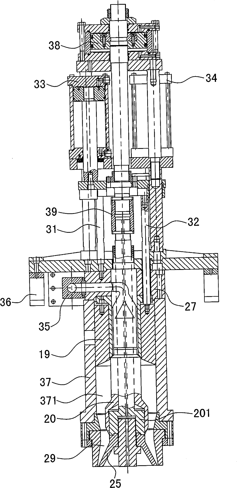
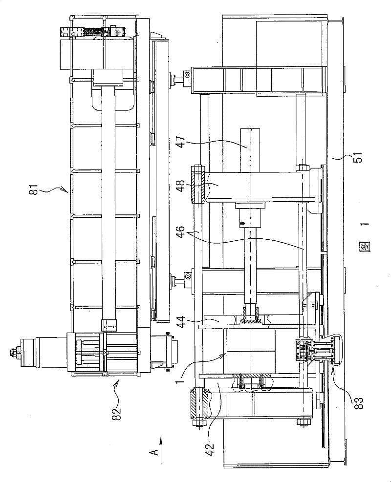
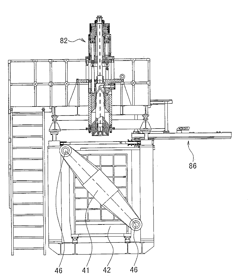
[0019] The invention discloses a plastic hollow container extrusion blowing machine, such as figure 1 , figure 2 As shown, it includes a plasticizing system 81 installed on the frame 51, a die extrusion system 82 and a blow molding system, and the plasticizing system includes a hopper, a barrel, a screw and an electric heating device; as Figure 6 As shown, the die head extrusion system 82 includes a die head support 36 installed on the frame 51, the die head support fixes the die head, and the die head includes a die head upper cover 27 and a die head body 37, inside the die head body A material storage cavity 371 is formed, and the upper cover of the die head is connected to the material cylinder and the material storage cavity through the joint neck 35. The material storage cavity 371 is equipped with an injection ring 19, and the injection ring is connected to the injection cylinder 33, 32 through the injection pillars 31 and 32. 34 piston rod; the lower end of the die h...


PUM


Abstract

A plastic hollow container extrusion blowing machine includes a plasticizing system installed on a frame, a die head extrusion system and a blow molding system. The blow molding system includes a blowing mechanism and a mold opening and closing mechanism. The mold opening and closing mechanism consists of The front template and the rear template connected by tie rods, the mold is installed between the front template and the middle template, the mold includes two cavities, and the opening and closing synchronous mechanism is installed between the middle and rear templates. The support rod groove, the base is fixed directly under the mold, the base is connected with the fixed plate through the up and down adjustment device, the fixed plate is installed with the lifting cylinder to connect the horizontal plate, the horizontal plate is fixed with the horizontal guide column through the left and right vertical plates, and the left and right vertical plates are installed with expansion cylinder A and expansion cylinder B. The direction of movement of the piston rods of the two expansion cylinders is opposite. The two piston rods fix the support block. The support rod is installed on the support block. The support rod is matched with the support rod groove. A blowing needle fixing block is installed in the middle of the horizontal guide column, and a blowing needle is installed on the blowing needle fixing block, and the blowing needle cooperates with the blowing hole at the bottom of the mould.

Description

technical field [0001] The invention relates to a extrusion blow molding machine for plastic hollow containers, which is used for manufacturing large-scale products such as oil drums, highway guardrails, etc., and small-scale products such as mineral water bottles, beverage bottles, medicine bottles, cosmetic bottles, etc., belonging to the field of plastic machinery manufacturing. Background technique [0002] The plastic hollow extrusion blow molding machine is the main equipment for forming hollow containers. First, the extruder extrudes the molten plastic into the die, and extrudes the material tube through the die. The material tube is located between the two cavities of the mold, and the mold is closed. The blowing mechanism injects air into the barrel, the product is blown into shape, the mold is opened, and the product is taken out. However, the existing extrusion blowing machines have the following defects: first, for large products, especially products with Φ>50...

Claims


Application Information

Patent Timeline
Patent Type & Authority Patents(China)
IPC IPC(8): B29C49/30B29C49/48B29C49/56B29C49/58B29C49/78B29C49/70B29L22/00
Inventor 施金亨
Owner 鼎浩(长兴)包装科技有限公司
Learn More