
Fixed-axis cycloid transmission device

A transmission device and fixed shaft technology, which is applied in the direction of transmission device, gear transmission device, belt/chain/gear, etc., can solve the problem of reducing transmission efficiency, transmission stability and carrying capacity, complicated installation and disassembly process, and high assembly precision requirements, etc. problem, to improve the transmission efficiency and transmission stability, simplify the installation and disassembly process, and expand the layout space.

Inactive Publication Date: 2011-07-20
CHONGQING UNIV
View PDF0 Cites 0 Cited by
  • Summary
  • Abstract
  • Description
  • Claims
  • Application Information

AI Technical Summary

Problems solved by technology

[0004] It can be seen from the above description that the structure of the prior art cycloidal pinwheel reducer is relatively complicated, the transmission chain is long, the transmission rigidity is poor, the transmission efficiency, the stability of the transmission and the carrying capacity are reduced, and the installation and disassembly process is relatively complicated. , high assembly precision requirements, low work efficiency

Method used


Image

  • Fixed-axis cycloid transmission device
  • Fixed-axis cycloid transmission device

Examples


Embodiment Construction

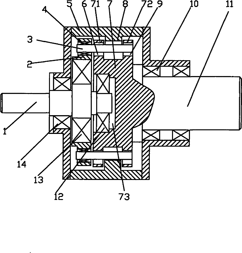
[0018] The accompanying drawing is a structural schematic diagram of the present invention, as shown in the figure: the fixed-axis cycloid transmission device of this embodiment includes a housing 5, a power input shaft 1 and a power output shaft that are coaxially arranged and respectively rotatably matched with the housing 5 11. In the figure, the power input shaft 1 and the power output shaft 11 are rotationally matched with the housing 5 through the rolling bearing 14 and the rolling bearing 10 respectively; The power take-off disk 7 is set in cooperation. In this embodiment, the power take-off shaft 11 and the power take-off disk 7 are fixedly matched in the circumferential direction by making one body to achieve the purpose of transmission cooperation; the drive disk 2 and the power take-off disk 7 Arranged side by side in the axial direction; evenly distributed along the circumferential direction of the driving disc 2, the transmission pin 3 is arranged to form a pin whe...


PUM


Abstract

The invention discloses a fixed-axis cycloid transmission device comprising a shell, a power input shaft and a power output shaft. The power input shaft and the power output shaft are coaxially arranged and are respectively in rotation match with the shell; a driving disk is arranged in eccentric transmission match with the excircle of the power input shaft; a power output disk is arranged in transmission match with the power output shaft; transmission pins are uniformly arranged in rotation match along the circumference direction of the driving disk to form a pin gear which is engaged with an involute inner gear fixedly arranged on the shell; and the transmission pins are in eccentric rotation match with the power output disk. In the fixed-axis cycloid transmission device, the bearing capability of a cycloid reducing mechanism is enhanced, and a cantilever pin output mechanism of a traditional pin gear reducer is not used any nore, and power is directly output by the power output disk driven by the revolution motion of the transmission pins so as to enhance the transmission rigidity, improve the transmission efficiency and the transmission stability and further improve the bearing capacity. The invention has simple structure, small size, light weight, low cost, simplified mounting and dismounting processes and improved working efficiency.

Description

technical field [0001] The invention relates to a reduction transmission mechanism, in particular to a fixed-axis cycloid transmission device. Background technique [0002] The field of reduction transmission device includes ordinary cylindrical gear reducer, planetary gear reducer, worm gear reducer, cycloid reducer, harmonic reducer and movable tooth reducer according to different application requirements, among which cycloid reducer has It has the advantages of simple structure, small size, large transmission ratio, strong carrying capacity and high efficiency. [0003] The cycloidal pinwheel reducer includes an input part, a deceleration part, and an output part; the input shaft is an eccentric shaft (or eccentric bearing, eccentric sleeve), and the center hole of the cycloidal wheel is sleeved on the eccentric shaft and meshed with the pinwheel to form a deceleration mechanism , when the input shaft rotates with the eccentric sleeve, because the motion of the cycloid w...

Claims


Application Information

Patent Timeline
Patent Type & Authority Patents(China)
IPC IPC(8): F16H1/32
Inventor 朱才朝肖宁张斌
Owner CHONGQING UNIV
Learn More