
Mesh weaving structure of hexagonal wire mesh weaving machine

A weaving machine and wire mesh technology, which is applied in braided fabrics, wire meshes, textiles, and papermaking, can solve the problems of short length of spring-shaped mesh, increased labor intensity, and complex structure, so as to achieve reasonable space layout and reduce labor intensity , the effect of improving work efficiency

Inactive Publication Date: 2017-09-08
定州市精锐机械科技有限公司
View PDF6 Cites 8 Cited by
  • Summary
  • Abstract
  • Description
  • Claims
  • Application Information

AI Technical Summary

Problems solved by technology

[0002] The wire twisting mechanism of the wire mesh knitting machine is equipped with a wire feeding device, which continuously feeds the wire to the wire twisting mechanism. However, because the twisting mechanism needs to rotate and twist the wire, the mesh behind the twisting mechanism will also rotate when twisting the wire. Phenomenon, so that the mesh behind the twisting mechanism will also be woven and cannot be processed normally and completely
In order to solve this phenomenon, the method adopted at present is to make a mesh wire into a spring shape and set it up behind the wire twisting mechanism, which not only has a complex structure but also greatly increases the labor intensity. Need to be replaced in time after time

Method used


Image

  • Mesh weaving structure of hexagonal wire mesh weaving machine
  • Mesh weaving structure of hexagonal wire mesh weaving machine
  • Mesh weaving structure of hexagonal wire mesh weaving machine

Examples


Embodiment 1

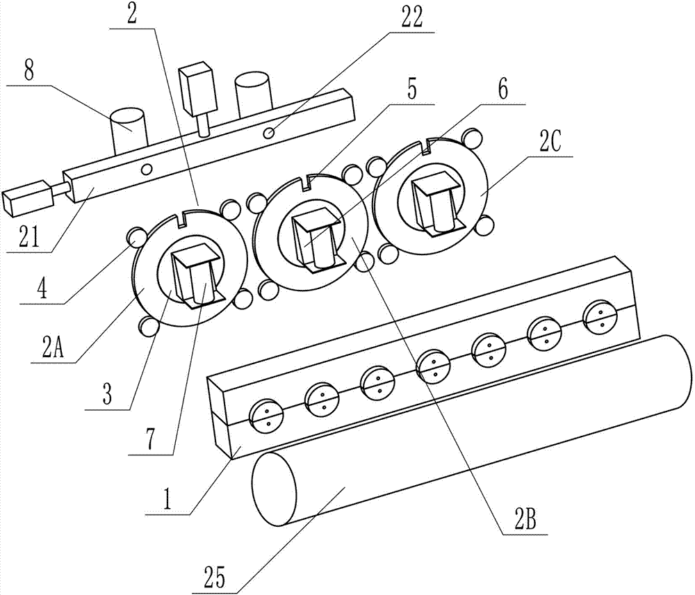
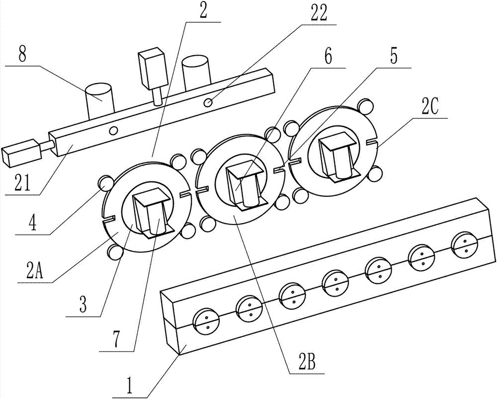
[0022] Embodiment 1: as attached figure 1 , 2 , 5, the present invention includes a wire twisting device 1 for twisting the mesh into the required shape of a hexagonal screen, a first wire feeding device 8 arranged behind the twisting device for feeding wire to the twisting device, The rotating device used to rotate the mesh wire is arranged between the first wire feeding device 8 and the wire twisting device. The rotating device includes more than two gear plates 2. Between the rotating device and the first wire feeding device 8 Between is provided with the wire pulling device that is used to dial the mesh wire from a gear plate 2 to the gear plate 2 adjacent to it and the second wire feeding device 7 that is used to feed the wire to the twisting device.

[0023] When the thread twisting device performs the thread twisting work, the mesh wire on the first wire feeding device 8 is rotated synchronously by the rotating device, which can effectively prevent the mesh silk behind...

Embodiment 2

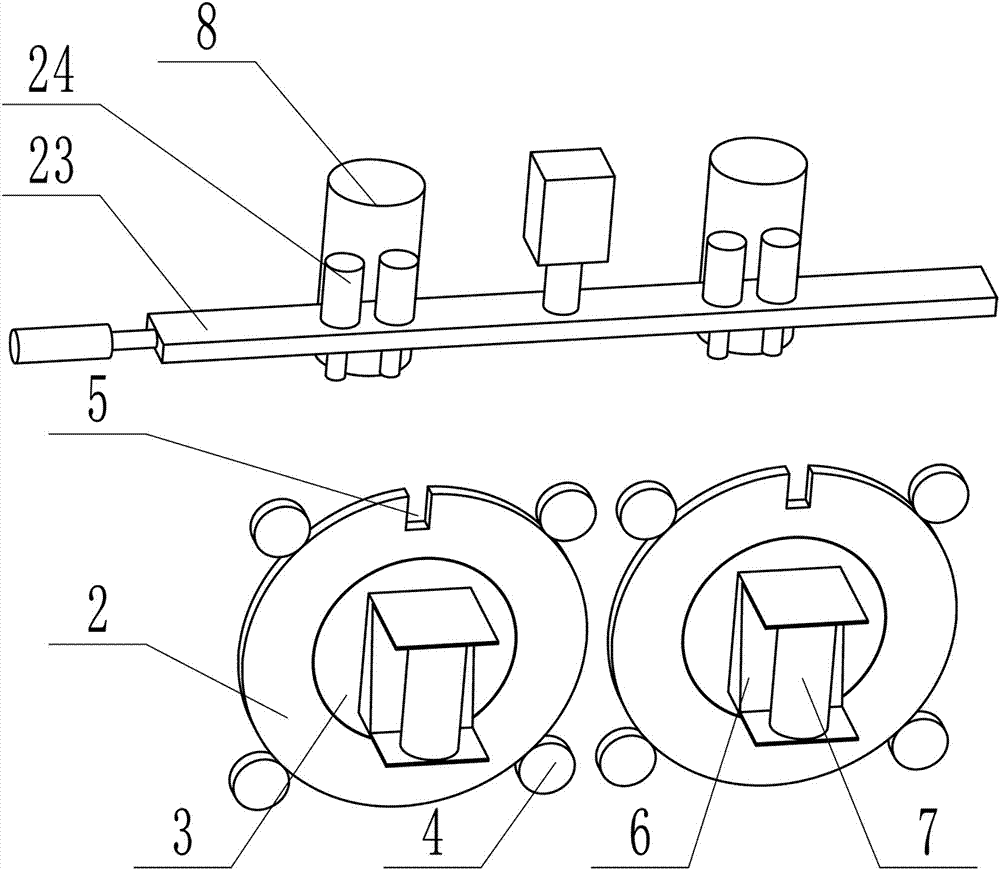
[0032] Embodiment 2: as attached image 3 As shown, on the basis of Embodiment 1, only the structure of the wire pulling device is changed, and the wire pulling device includes a connecting plate 23 capable of moving in the horizontal and vertical directions, and is arranged on the connecting plate 23 for carrying out wire meshing. Limiting cylinder group 24, the position of the cylinder group 24 corresponds to the position of the gear plate 2, the cylinder group 24 includes two cylinders, the cylinder body of the cylinder is arranged on the upper side of the connecting plate, and the cylinder of the cylinder The rod passes through the connecting plate on the underside of the connecting plate.

[0033] In the initial state, the slots 5 of the gear plate 2 are all vertically upward.

[0034] When this embodiment is in use, the cylinder rods of the cylinder group 24 stretch out from the connecting plate 23, and the space between the cylinder rods of the two cylinders forms a sp...

Embodiment 3

[0035] Embodiment 3: as attached Figure 4 As shown, on the basis of Embodiment 1, the structure of the wire pulling device and the rotating device is changed. The rotating device is arranged in more than one group in sequence and the setting direction is the same as that of the screwing device 1. Each group of the rotating device It includes four gear discs 2 and a driving device for driving the gear discs 2 to rotate. The four gear discs are arranged in a rectangular array, and the outer edge of each of the gear discs 2 is provided with a device for clamping the first wire feeding device. 8 provides two mesh slots 5, the slots 5 are two, and the angle between the two slots 5 and the center line of the corresponding gear plate 2 is 90°. The four gear plates 2 are defined as a gear plate 2a, b gear plate 2b, c gear plate 2c and d gear plate 2d, and are arranged at four vertices of the quadrilateral in turn. Under the action of the dialing device, the first The mesh wire of th...


PUM


Abstract

The invention relates to a mesh weaving structure of a hexagonal wire mesh weaving machine. The mesh weaving structure comprises a wire twisting device, first wire feeding devices, rotating devices, a wire poking device and second wire feeding devices; the first wire feeding devices are arranged behind the wire twisting device and used for feeding wires to the wire twisting device, the rotating devices are arranged between the first wire feeding devices and the wire twisting device and used for enabling the mesh wires to rotate, the wire poking device is arranged between the rotating devices and the first wire feeding devices and used for poking the mesh wires from one gear disc to a gear disc located at the adjacent position of the gear disc, and the second wire feeding devices are used for feeding the wires to the wire twisting device. According to the mesh weaving structure of the hexagonal wire mesh weaving machine, the gear discs used for enabling the mesh wires to rotate are arranged behind the wire twisting device, therefore, the condition that the mesh wires located behind the wire twisting device are woven when weaving is conducted can be effectively prevented, it is guaranteed that the weaving work is smoothly conducted, a spring-shaped mesh wire structure is omitted, and the labor intensity of workers is greatly reduced; meanwhile, the using time of the first wire feeding devices is long, therefore, frequent replacement is not needed, and the working efficiency is improved.

Description

technical field [0001] The invention relates to the field of screen production, in particular to a weaving structure of a hexagonal screen weaving machine. Background technique [0002] The wire twisting mechanism of the wire mesh knitting machine is equipped with a wire feeding device, which continuously feeds the wire to the wire twisting mechanism. However, because the twisting mechanism needs to rotate and twist the wire, the mesh behind the twisting mechanism will also rotate when twisting the wire. Phenomenon, in this way, the mesh wire behind the twisting mechanism will also be woven and cannot be processed normally and completely. In order to solve this phenomenon, the method adopted at present is to make a mesh wire into a spring shape and set it up behind the wire twisting mechanism, which not only has a complex structure but also greatly increases the labor intensity. It needs to be replaced in time after the time. Contents of the invention [0003] The techni...

Claims


Application Information

Patent Timeline
Patent Type & Authority Applications(China)
IPC IPC(8): B21F27/06B21F23/00D04C3/00D04C3/48
CPCB21F27/06B21F23/00D04C3/00D04C3/48
Inventor 高海明高海亮高山森高山天方高雨川
Owner 定州市精锐机械科技有限公司
Learn More