Rotary type engine

A rotary engine and rotor technology, applied in the direction of combustion engine, machine/engine, internal combustion piston engine, etc., can solve the problems of large ineffective energy consumption, high mechanical wear, and pollution of exhaust emissions, and achieve easy manufacturing and simple structure Effect

Inactive Publication Date: 2010-01-27
邵本琦
View PDF0 Cites 0 Cited by
  • Summary
  • Abstract
  • Description
  • Claims
  • Application Information

AI Technical Summary

Problems solved by technology

Due to the limitation of the structure, it must be realized by constantly changing the direction of the force, which increases the loss of reactive power and parts, and also limits the stroke of the piston, restricts the improvement of the air compression ratio, and affects the output of effective power.
[0003]For example, the current four-stroke engine, due to its structure, leads to high mechanical wear, low thermal efficiency, large ineffective energy consumption, and polluting exhaust emissions

Method used


Image

  • Rotary type engine

Examples


Embodiment Construction

[0034] Specific embodiments are given below in conjunction with the accompanying drawings to further illustrate how the rotary engine of the present invention is realized.

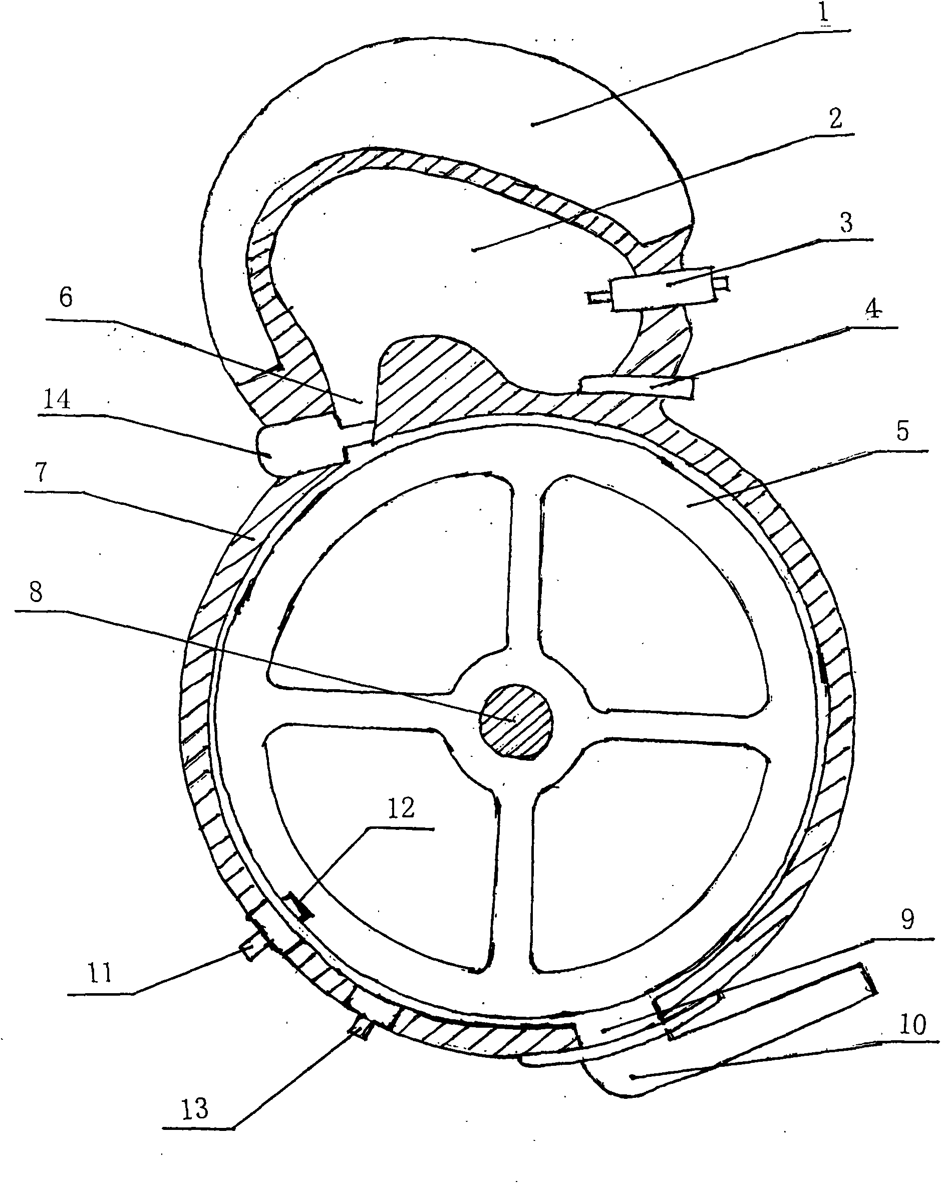
[0035] Such as figure 1 As shown, the rotary engine of the present invention includes a casing 7, a rotor 5 is arranged in the casing 7, a rotor shaft 8 is fixedly arranged on the shaft center of the rotor 5, and a rotor shaft 8 of the rotor shaft 8 is fixed. Both ends stretch out the two ends of housing 7 for output power, integrally form active explosion chamber 2 on the side wall of housing 7, described power explosion chamber 2 and housing 7 are formed between the two The impact nozzle 6 communicates with each other, and the side wall of the power explosion chamber 2 is respectively provided with an air intake nozzle 4 and a high-energy igniter 3, and the impact nozzle 6 is provided with a solenoid valve 14 connected with the control unit for controlling the opening and closing of the port, On the sid...


PUM


Abstract

The invention discloses a rotary type engine which is characterized in that a rotor is arranged in a shell, a rotor shaft is fixedly arranged on the shaft center of the rotor, both ends of the rotor shaft which stretches out both ends of the shell are used for outputting power, a power explosion room is formed on one side wall of the shell; the power explosion room is communicated with the shell by an impacting nozzle formed between the power explosion room and the shell; an air inlet nozzle and a high energy igniter are respectively arranged on the side wall of the power explosion room; the impacting nozzle is provided with a solenoid valve; an exhaust port is opened on the side wall of one side of the shell which is opposite to the power explosion room and is connected with an exhaust pipe which is used for discharging air in the interior of the shell to the exterior. The shell wall of the shell is provided with a first approaching sensor and a second approaching sensor which are connected with a control part; the periphery of the rotor, the first approaching sensor and the second approaching sensor are correspondingly provided with magnetic pots. The rotary type engine has low mechanical wear, non tail gas discharging pollution and high heat efficiency and can provide power of a high speed generator for large scale locomotives and ships.

Description

technical field [0001] The invention relates to an engine, in particular to a rotary engine with less mechanical wear, high thermal efficiency and zero pollution. Background technique [0002] Present existing piston engines all continue to use the crankshaft connecting rod device to conduct the vertical vector when the piston does work. Due to the limitation of the structure, it must be realized by constantly changing the direction of the force, which increases the loss of reactive power and parts, and also limits the stroke of the piston, restricts the improvement of the air compression ratio, and affects the output of effective power. [0003] For example, the current four-stroke engine, due to its structure, causes high mechanical wear, low thermal efficiency, large ineffective energy consumption, and polluting exhaust emissions. Contents of the invention [0004] The technical problem to be solved by the present invention is to provide a rotary engine with small mech...

Claims


Application Information

Patent Timeline
Patent Type & Authority Applications(China)
IPC IPC(8): F02B53/02F02B55/14F02B55/16F02B55/10F02B55/02
CPCY02T10/17Y02T10/12
Inventor 邵本琦
Owner 邵本琦
Why Eureka
Try Eureka