U-shaped tube type heat exchanger
A tube-and-tube heat exchanger and U-shaped tube technology, applied in indirect heat exchangers, heat exchanger types, solar collectors, etc., can solve problems such as poor rigidity, transportation, installation and maintenance difficulties, and achieve the goal of using The effect of long life, compact structure and easy manufacturing
- Summary
- Abstract
- Description
- Claims
- Application Information
AI Technical Summary
Problems solved by technology
Method used
Image
Examples
Embodiment Construction
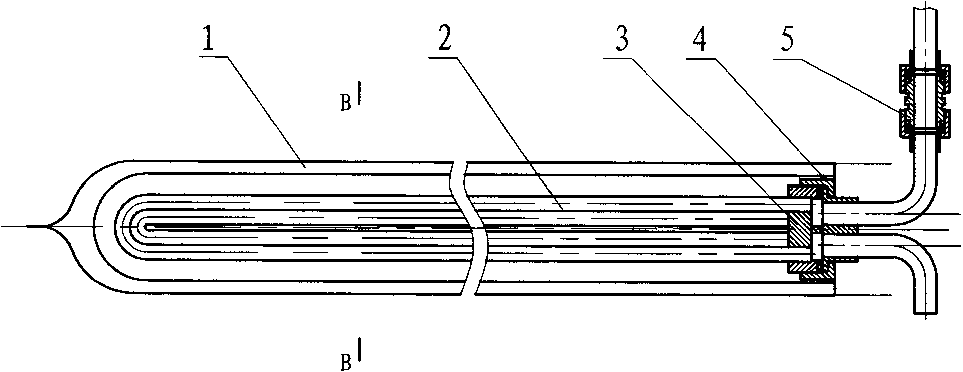
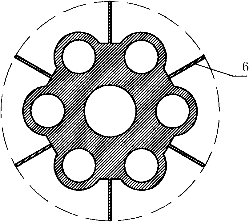
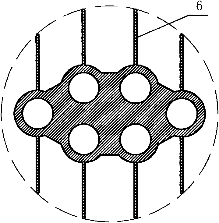
[0024] As shown in the figure, the flow channel chamber 3 is composed of a flower plate 8 with a through hole and an end cover 10. A cavity is formed between the flower plate and the end cover, and an O-ring 11 is arranged between the flower plate and the end cover to seal the cavity. The middle part is provided with a partition 9 to divide it into left and right chambers. The flower plate 8 is threadedly connected with the compression nut 7, and the end cover 10 and the flower plate 8 are compressed and sealed. An inlet and outlet connecting pipe is arranged on the end cover. The flow channel chamber 3 is arranged at the heat collecting nozzle, and the high temperature resistant silicone ring 4 is used to seal between the flow channel chamber and the heat collecting nozzle. One end of every two parallel pipes is welded with a U-shaped pipe elbow to form a U-shaped tube, and a U-shaped tube bundle 2 composed of three sets of U-shaped tubes is used. The tube holes are arranged...
PUM
 Abstract
Description
Claims
Application Information
 - R&D
- Intellectual Property
- Life Sciences
- Materials
- Tech Scout
- Unparalleled Data Quality
- Higher Quality Content
- 60% Fewer Hallucinations
Browse by: Latest US Patents, China's latest patents, Technical Efficacy Thesaurus, Application Domain, Technology Topic, Popular Technical Reports.
© 2025 PatSnap. All rights reserved.Legal|Privacy policy|Modern Slavery Act Transparency Statement|Sitemap|About US| Contact US: help@patsnap.com


