Luminous element drive circuit and method thereof

A technology of light-emitting elements and driving circuits, which can be applied to the layout of electric lamp circuits, light sources, electric light sources, etc., and can solve problems such as design troubles and inconvenient use for users

Inactive Publication Date: 2010-01-06
ITE TECH INC
View PDF0 Cites 14 Cited by
  • Summary
  • Abstract
  • Description
  • Claims
  • Application Information

AI Technical Summary

Problems solved by technology

[0005] However, since the timing generation circuit 202 depends on the timing control signal EXCS to change the timing of the conduction control signal TS, when the variation range of the inductor current IL exceeds the maximum current value I MAX with minimum current value I MIN When it is necessary to change the timing of the conduction control signal TS within the defined range, the user must modify the circuit that provides the timing control signal EXCS to change the timing control signal EXCS, otherwise the inductance value of the inductor 214 must be changed, or the The number of light-emitting diodes in the light-emitting diode string 212 can only be reached, causing inconvenience to users
And if the LED driving circuit is made into a circuit chip, there must be an extra pin (pin) to couple with the external circuit that provides the timing control signal EXCS, which also causes design troubles.

Method used


Image

  • Luminous element drive circuit and method thereof
  • Luminous element drive circuit and method thereof
  • Luminous element drive circuit and method thereof

Examples


Embodiment Construction

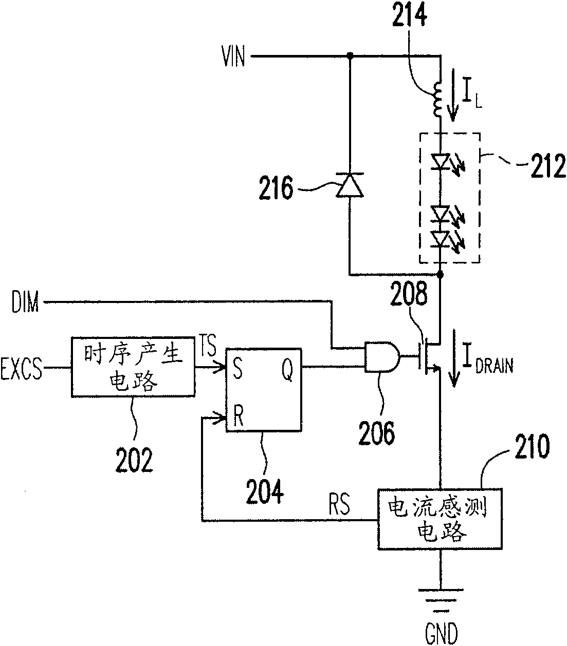
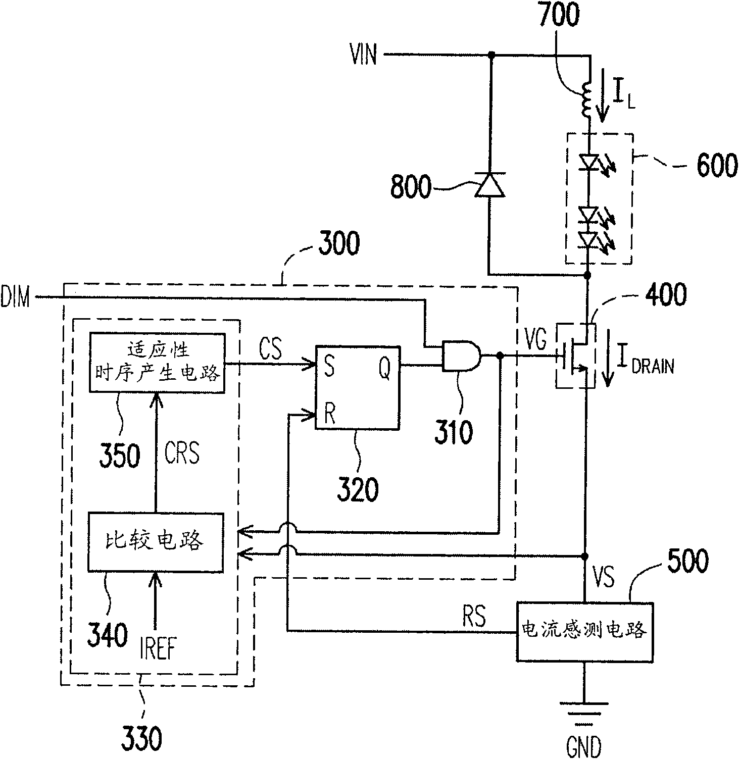
[0063] image 3 A light-emitting device driving circuit and a coupling method thereof according to an embodiment of the present invention. The light-emitting device driving circuit is composed of a switch control circuit 300 , a switch 400 and a current sensing circuit 500 for driving the light-emitting device 600 . Wherein, one end of the light emitting element 600 is coupled to the power supply voltage VIN and the cathode of the diode 800 through the inductor 700 , and the other end of the light emitting element 600 is coupled to the anode of the diode 800 . In this example, the light-emitting element 600 is composed of a plurality of light-emitting diodes connected in series, and the power supply voltage VIN is a DC voltage, and the switch 400 is realized by an NMOS transistor. Of course, the switch 400 can also be composed of other types of transistors such as PMOS transistors or BJTs.

[0064] A first end of the switch 400 is coupled to the other end of the light emitti...


PUM


Abstract

A luminous element drive circuit and a method thereof are disclosed. One end of the luminous element is coupled to a power voltage and the cathode of a diode by an inductor, and the other end thereof is coupled to the anode of the diode. The luminous element drive circuit comprises a switch, a current sensing circuit and a switch control circuit. The current sensing circuit is coupled to the anode of the diode by the switch and used for deciding whether to generate closing control signals according to the breakover current value of the switch. The switch control circuit is used for controlling the breakover and closing of the switch and can close the switch according to the closing control signals. In addition, the switch control circuit is also used for comparing the breakover current value of the switch with a reference current value, so as to generate comparison result to dynamically adjust the time length for closing the switch.

Description

technical field [0001] The present invention relates to a driving circuit and its method, and in particular to a light-emitting element driving circuit and its method. Background technique [0002] figure 1 A conventional LED driving circuit of a buck type with current sensing performed at the source of a MOS transistor and its coupling are shown. The light emitting diode (light emitting diode, LED) driving circuit is composed of a timing generating circuit 202, a positive-edge triggered SR latch 204, an AND gate 206, a switch 208 realized by an NMOS (N-type metal oxide semiconductor) transistor, and a current sense The detection circuit 210 is used to drive the LED string 212 composed of a plurality of LEDs. Of course, the switch 208 may also be composed of PMOS (P-type metal oxide semiconductor) transistors or bipolar junction transistors (bipolar junction transistors, BJT) . . . and other types of transistors. exist figure 1 Among them, one end of the LED string 212 i...

Claims


Application Information

Patent Timeline
Patent Type & Authority Applications(China)
IPC IPC(8): H05B37/02
CPCY02B20/42Y02B20/40
Inventor 蔡明衡周宜群
Owner ITE TECH INC
Why Eureka
Try Eureka