Automatic locking drawbar coupling

A technology of automatic locking and coupling

Inactive Publication Date: 2020-01-24
LOHR ELECTROMECANIQUE
View PDF1 Cites 0 Cited by
  • Summary
  • Abstract
  • Description
  • Claims
  • Application Information

AI Technical Summary

Problems solved by technology

In fact, if this locking is not correct, the operator may also be led to think that the vehicle is well coupled and to drive with said vehicle, which may cause serious accidents in the event of a coupling failure

Method used


Image

  • Automatic locking drawbar coupling
  • Automatic locking drawbar coupling
  • Automatic locking drawbar coupling

Examples


Embodiment Construction

[0045] Structurally and functionally identical elements shown in several different figures are given the same numerical or alphanumeric designations.

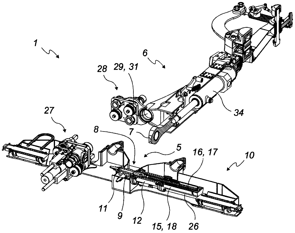
[0046] A coupling device (1) according to the invention is intended for positioning between a first road vehicle (2) and an adjacent second road vehicle (3) for coupling the two road vehicles (2, 3).

[0047] The expressions "first vehicle" and "second vehicle" are not to be interpreted for any relative positioning or any role of these vehicles, but merely to allow them to be distinguished from each other.

[0048] According to a preferred embodiment of the invention, the first road vehicle (2) is a motor tractor vehicle positioned in front of the second road vehicle (3), which is the following vehicle.

[0049] The coupling device (1) according to the invention is intended to equip road vehicles (2, 3) each comprising at least two wheel axles (4). Preferably, it concerns a vehicle intended to transport people.

[0050] Such ...


PUM


Abstract

A drawbar (6) attached to a second road vehicle (3) comprises a coupling eye (7) at its end, while a crossbar (10) attached to a first road vehicle (2) comprises a drawbar coupling (5) intended to accept the coupling eye (7) of the first road vehicle (2) that locks when the two road vehicles (2, 3) are coupled. An automatic locking mechanism is provided to lock the coupling eye (7) to the drawbarcoupling (5) automatically when it enters the drawbar coupling (5) once the coupling eye (7) and the drawbar coupling (5) have been brought closer together.

Description

technical field [0001] The invention relates to a coupling device intended to couple two road vehicles each comprising at least two axles. [0002] More specifically, the present invention relates to a coupling device comprising a hitch coupling secured to one vehicle and a hitch secured to another vehicle, wherein the hitch includes an end coupling eyelet portion intended to enter and lock on the hitch In the coupling, in order to connect two vehicles. Background technique [0003] In coupling devices intended to couple two road vehicles, it is known to equip one of the vehicles with a hitch comprising an end coupling eye portion. The coupling eyelet is intended to enter into a hitch coupling of another vehicle and is locked there by inserting a coupling pin into the central opening of the eyelet. [0004] Insertion of the coupling eyelet into the hitch coupling is usually done by moving one vehicle to be coupled closer to the other vehicle. In contrast, the insertion of...

Claims


Application Information

Patent Timeline
Patent Type & Authority Applications(China)
IPC IPC(8): B60D1/48B60D1/02B60D1/26B60D1/62
CPCB60D1/02B60D1/025B60D1/26B60D1/481B60D1/62
Inventor 丹尼尔·舍尔迪迪埃·甘特尔让-吕克·安德烈尼古拉斯·萨特
Owner LOHR ELECTROMECANIQUE
Why Eureka
Try Eureka