
Single phase permanent magnetic mechanism for vacuum circuit breaker

A vacuum circuit breaker and single-phase permanent magnet technology, which is applied to high-voltage air circuit breakers, circuits, electrical components, etc., can solve the problems of large cumulative motion tolerance, many transmission links, and restrictions on synchronous closing technology, and achieve cumulative motion tolerance Small, achieve synchronous closing, and reduce the effect of occupying space

Inactive Publication Date: 2009-12-30
NANJING INTELLIGENT DISTRIBUTION AUTOMATION EQUIP
View PDF0 Cites 12 Cited by
  • Summary
  • Abstract
  • Description
  • Claims
  • Application Information

AI Technical Summary

Problems solved by technology

[0003] Although the three-phase split permanent magnet operating mechanism vacuum circuit breaker has obvious advantages compared with other switches in terms of switching capacitor banks, it still cannot meet the requirements of synchronous closing
The main reason is that there are many transmission links in the operating mechanism, and the cumulative motion tolerance is large, so that the response time is highly dispersed, and the accurate positioning of the voltage or current rubber at the moment of opening and closing cannot be realized, which restricts the realization of synchronous closing technology.

Method used


Image

  • Single phase permanent magnetic mechanism for vacuum circuit breaker
  • Single phase permanent magnetic mechanism for vacuum circuit breaker
  • Single phase permanent magnetic mechanism for vacuum circuit breaker

Examples


Embodiment Construction

[0010] In order to make the above and other objects, features and advantages of the present invention more comprehensible, preferred embodiments are described below in detail with accompanying drawings.

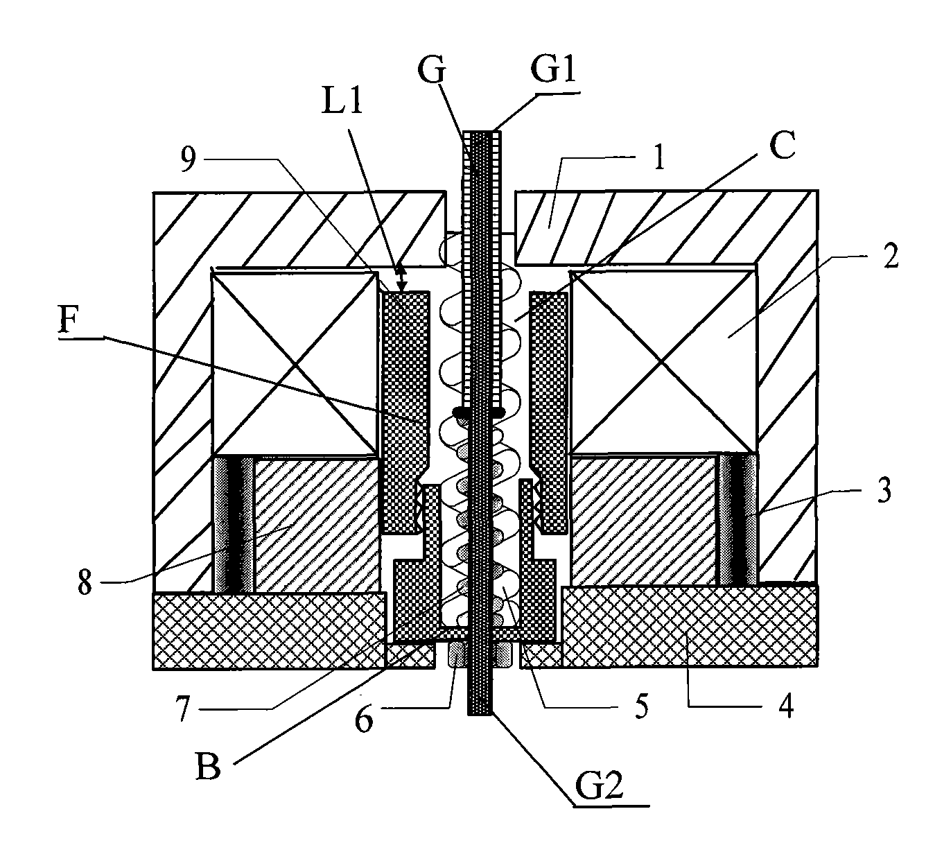
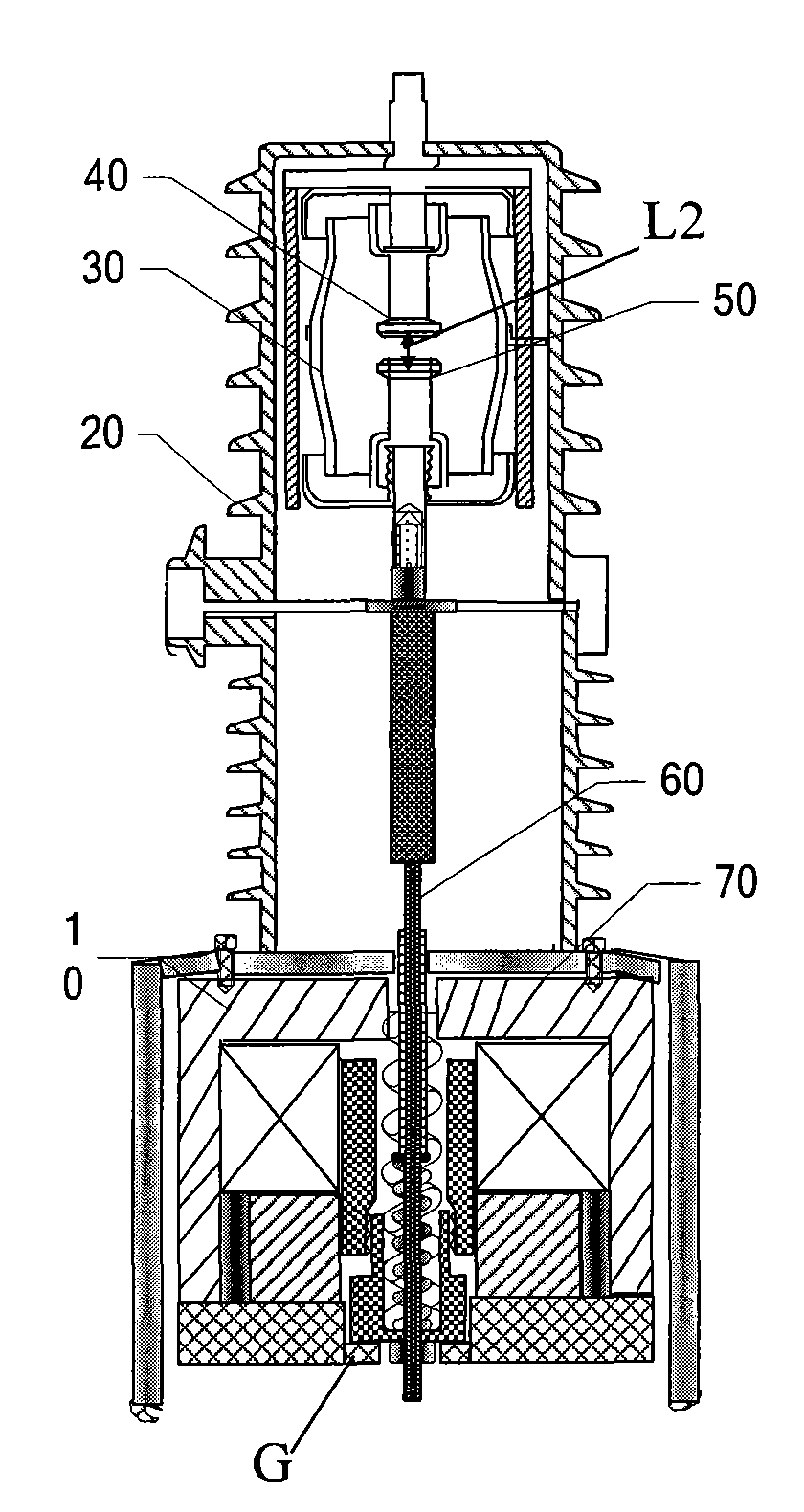
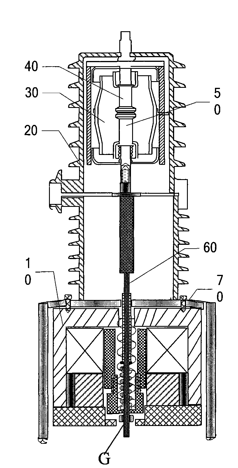
[0011] figure 1 It is a structural schematic diagram of a vacuum circuit breaker single-phase permanent magnet mechanism according to an embodiment of the present invention. Figure 2a to have figure 1 Schematic diagram of the structure of the vacuum circuit breaker body of the single-phase permanent magnet mechanism when it is opened. Figure 2b to have figure 1 Schematic diagram of the structure of the vacuum circuit breaker body of the single-phase permanent magnet mechanism when it is closed. The vacuum circuit breaker body includes an insulating sleeve 20, a vacuum interrupter 30, a static contact 40, a moving contact 50, and a connecting rod 60. The specific connection relationship and working principle of each component in the vacuum circuit breaker body are general...


PUM


Abstract

The invention provides a single phase permanent magnetic mechanism for a vacuum circuit breaker, which comprises an upper end cover, a lower end cover, a moveable iron core, an insulating tension rod, a closing coil, a permanent magnet, a conductive magnet, a contact spring and a breaking spring. The mechanism has fewer transmission links, small installation volume, small difference of accumulated motion, and small dispersity of action response time, and can accurate positioning of a phase angle of voltage or current at breaking time and closure time, thereby realizing synchronous closure.

Description

technical field [0001] The present invention relates to a permanent magnet mechanism, and in particular to a vacuum circuit breaker single-phase permanent magnet mechanism. Background technique [0002] With the development of the power system, users have higher and higher requirements for power supply quality. The capacitor bank is an important reactive power source in the power system, which is used to compensate the system reactive power loss and stabilize the system voltage. Therefore, in The requirements for switching capacitor bank switches in power systems are getting higher and higher. At present, it is more popular to use three-phase split type permanent magnet operating mechanism vacuum circuit breaker to realize three-phase phase selection and combination operation to meet various compensation methods. Each of the three phases of the vacuum circuit breaker should be equipped with an independent permanent magnet mechanism (single-phase permanent magnet mechanism)....

Claims


Application Information

Patent Timeline
IPC IPC(8): H01H33/666H01H33/38
Inventor 林莘田阳王博徐陆飞孙浩童利琴
Owner NANJING INTELLIGENT DISTRIBUTION AUTOMATION EQUIP
Learn More