Radiator and manufacturing method thereof

A manufacturing method and radiator technology, applied in the direction of instruments, instrument cooling, instrument parts, etc., can solve the problems of poor convection heat dissipation effect and unsatisfactory heat dissipation effect, so as to prevent heat retention, strengthen convection heat dissipation effect, The effect of reducing production costs

Inactive Publication Date: 2009-12-30
ZHEJIANG JINGRI LIGHTING TECH
View PDF0 Cites 1 Cited by
  • Summary
  • Abstract
  • Description
  • Claims
  • Application Information

AI Technical Summary

Problems solved by technology

When dissipating heat, the heat is mostly conducted upwards from the bottom edge of the cooling fins to the surface of the cooling fins through conduction, and then the heat on the surface of the cooling fins is taken away by the cooling fan. The convective cooling effect is poor, and the overall cooling effect is not good. very ideal

Method used


Image

  • Radiator and manufacturing method thereof
  • Radiator and manufacturing method thereof
  • Radiator and manufacturing method thereof

Examples


Embodiment Construction

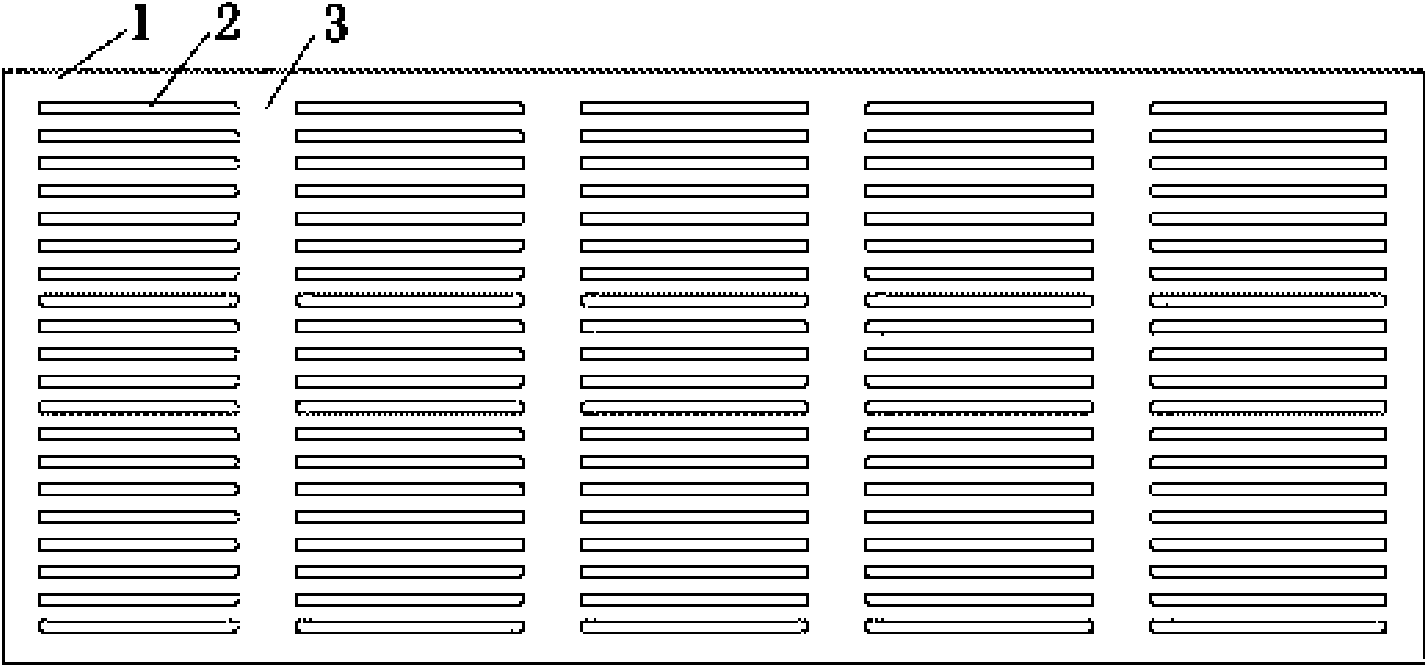
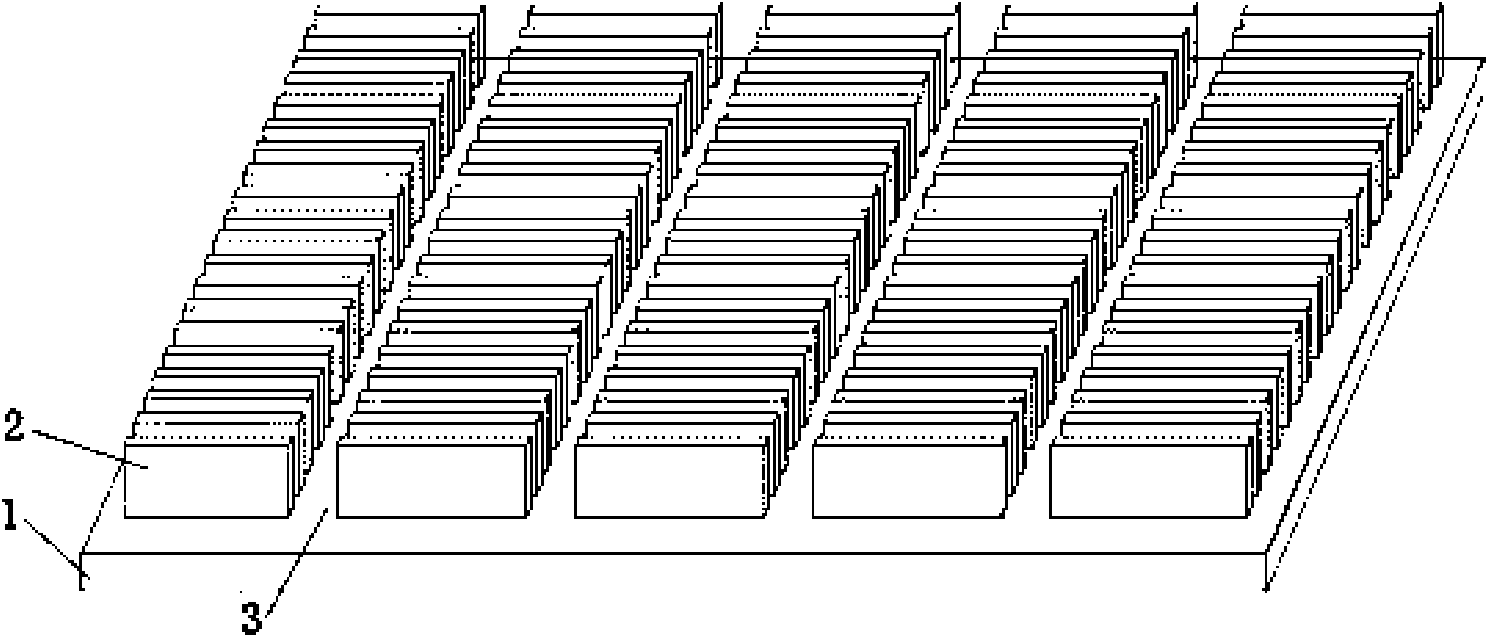
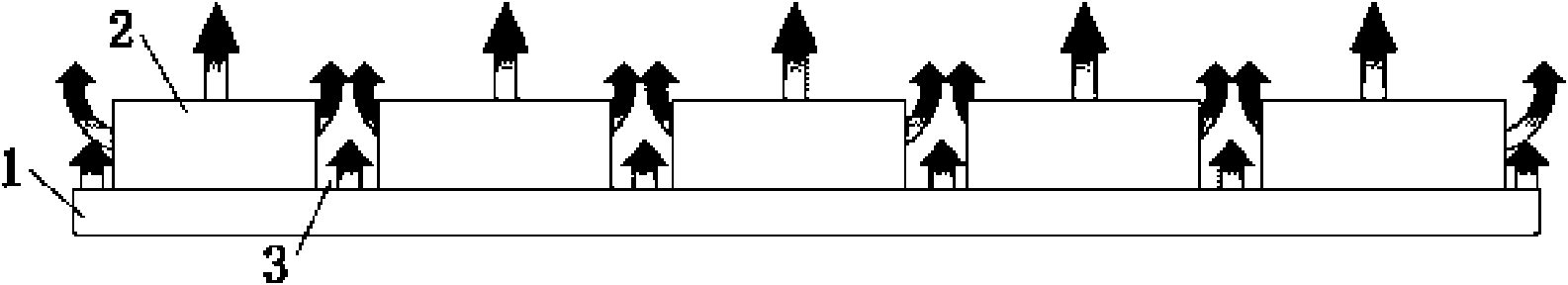
[0014] Example. Such as figure 1 , figure 2 As shown, the radiator of the present invention includes a radiator base 1 and cooling fins 2 , and the cooling fins 2 are fixedly mounted on the radiator base 1 . A convection groove 3 is provided between two adjacent groups of heat dissipation fins 2. The convection groove 3 divides the heat dissipation fins 2 into several sections, forming a certain convection space between the heat dissipation fins 2, which is beneficial to the heat dissipation of the heat dissipation fins. 2 convection heat dissipation, the thermal diagram is shown in image 3 shown. Depending on the arrangement of the heat dissipation fins 2, the convection grooves 3 can be horizontal grooves or longitudinal grooves, that is, when the heat dissipation fins 2 are arranged horizontally, the convection grooves 3 are longitudinal grooves; When the fins 2 are arranged vertically, the convection grooves 3 are horizontal grooves.

[0015] During manufacture, the...


PUM


Abstract

The invention discloses a radiator and a manufacturing method thereof. The method reserves longitudinal grooves between transversely arranged radiating fins or transverse grooves between longitudinally arranged radiating fins to arrange the transversely arranged radiating fin groups or the longitudinally arranged radiating fin groups at intervals and to disconnect the radiating fin groups, thereby increasing convection radiation space between the radiating fin groups and improving convection radiation effect. By arranging convection grooves between two adjacent groups of radiating fins, the method increases convection radiation space between the radiating fins, prevents heat residue caused by small radiation space between the radiating fins, improves the convection radiation effect of the radiating fins, ensures the extremely ideal overall radiation effect of an radiator, saves materials of the radiating fins and reduces enterprise production cost.

Description

technical field [0001] The invention relates to a heat sink structure and a manufacturing method of the heat sink. Background technique [0002] A traditional heat sink is composed of a heat sink base and a number of heat dissipation fins arranged in parallel on the heat sink base. The heat dissipation fins are usually long strips, and the heat dissipation fins are arranged horizontally or vertically at a certain distance. Since the distance between the heat dissipation fins is often relatively small, the convection space between the heat dissipation fins is narrow, and a large amount of heat is retained between the heat dissipation fins. When dissipating heat, the heat is mostly conducted upwards from the bottom edge of the cooling fins to the surface of the cooling fins through conduction, and then the heat on the surface of the cooling fins is taken away by the cooling fan. The convective cooling effect is poor, and the overall cooling effect is not good. Ideal. Conten...

Claims


Application Information

Patent Timeline
Patent Type & Authority Applications(China)
IPC IPC(8): G12B15/06
Inventor 程世友傅创业
Owner ZHEJIANG JINGRI LIGHTING TECH
Why Eureka
Try Eureka