
Sealing dustproof method and sealing dustproof device of bell-less furnace top gas seal box

A technology of dust-proof device and airtight box, which is applied in the arrangement of bells and funnels, can solve problems such as inability to seal, and achieve a good sealing effect

Active Publication Date: 2009-12-30
SHANDONG IRON & STEEL CO LTD
View PDF1 Cites 10 Cited by
  • Summary
  • Abstract
  • Description
  • Claims
  • Application Information

AI Technical Summary

Problems solved by technology

Chinese patent document CN2581459 discloses a sealing device for the airtight box of a chute distributor. This invention only has a sealing effect on the annular gap between the rotating chassis and the chute cylinder, and has a sealing effect on the gap between the chute bracket and the rotating chassis. Large transmission gap cannot be sealed

Method used


Image

  • Sealing dustproof method and sealing dustproof device of bell-less furnace top gas seal box
  • Sealing dustproof method and sealing dustproof device of bell-less furnace top gas seal box

Examples


Embodiment 1

[0020] Embodiment 1: refer to figure 2 .

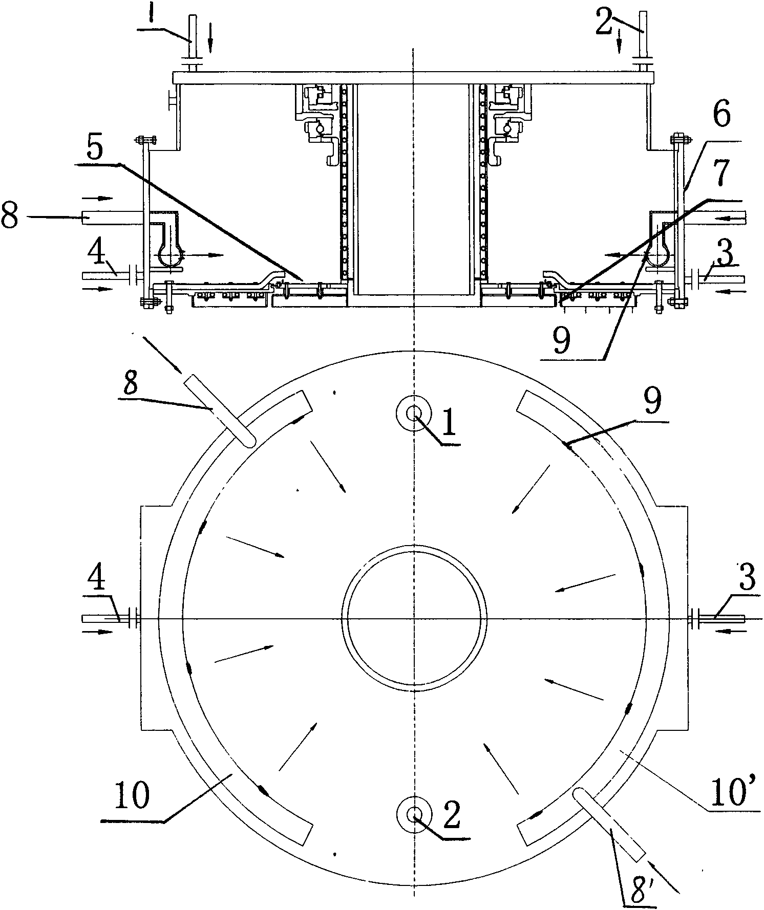
[0021] A method for sealing and dust-proofing an airtight box at the top of a bell furnace, on the basis of four nitrogen purge points in the prior art, the following content is added: two semi-annular pipes 10, 10', a row of small purge holes 9 are evenly opened inside the semi-annular pipe, and nitrogen gas is passed into the two semi-annular pipes so that the nitrogen passes through the small purge holes 9 on the inside of the semi-annular pipe toward the rotating chassis 5 and the airtight box The annular seam between 7 directions (such as figure 2 arrow), when the nitrogen pressure is higher than the pressure in the furnace, an air curtain is formed in the circular seam between the transmission mechanism and the stationary box 7 circles, and the air curtain is opposite to the chassis when the rotating chassis 5 rotates. Perform purging while blocking external dust from rushing into the box.

Embodiment 2

[0023] The sealing and dustproof device and installation structure of the airtight box are as follows: figure 2 As shown, at the annular seam 7 between the rotating chassis 5 and the box body, two semi-annular pipes 10, 10' are installed and fixed inside the box body, and the two nitrogen gas inlet pipes 8, 8' are connected to the two semi-annular pipes respectively. 10, 10', 16 small purge holes 9 are evenly opened inside the semi-circular pipe, and the small holes 9 form a nitrogen curtain, which plays the role of active sealing and effectively prevents the deposition of dust in the furnace.

[0024] The semi-annular pipe is made of a steel pipe with a diameter of 40 mm to make a circle according to the inner diameter of the box, and then divided into two semi-annular pipes for installation. figure 2 As shown by the arrow in the top view), there are 16 small holes 9 of 10mm in total. These small holes 9 form an air curtain around the 7th ring seam, which not only prevents ...


PUM


Abstract

The invention relates to a sealing dustproof method and a sealing dustproof device of a bell-less furnace top gas seal box. The sealing dustproof method comprises the steps: two nitrogen blowing points are respectively arranged at the upper part and the lower part of the gas seal box, and semi-ring pipes are provided with holes at two inner sides and are arranged at the inner side of a box body of the gas seal box, nitrogen is led into the two semi-ring pipes so as to lead the nitrogen to be injected out towards a circular seam between a rotating bottom disk and the box body of the gas seal box through the blowing holes of the inner sides of the semi-ring pipes, a gas curtain is formed at the periphery of the circular seam and blows the bottom disk when the bottom disk rotates and blocks the outside dust to rush into the box body, thereby playing a role of actively sealing.

Description

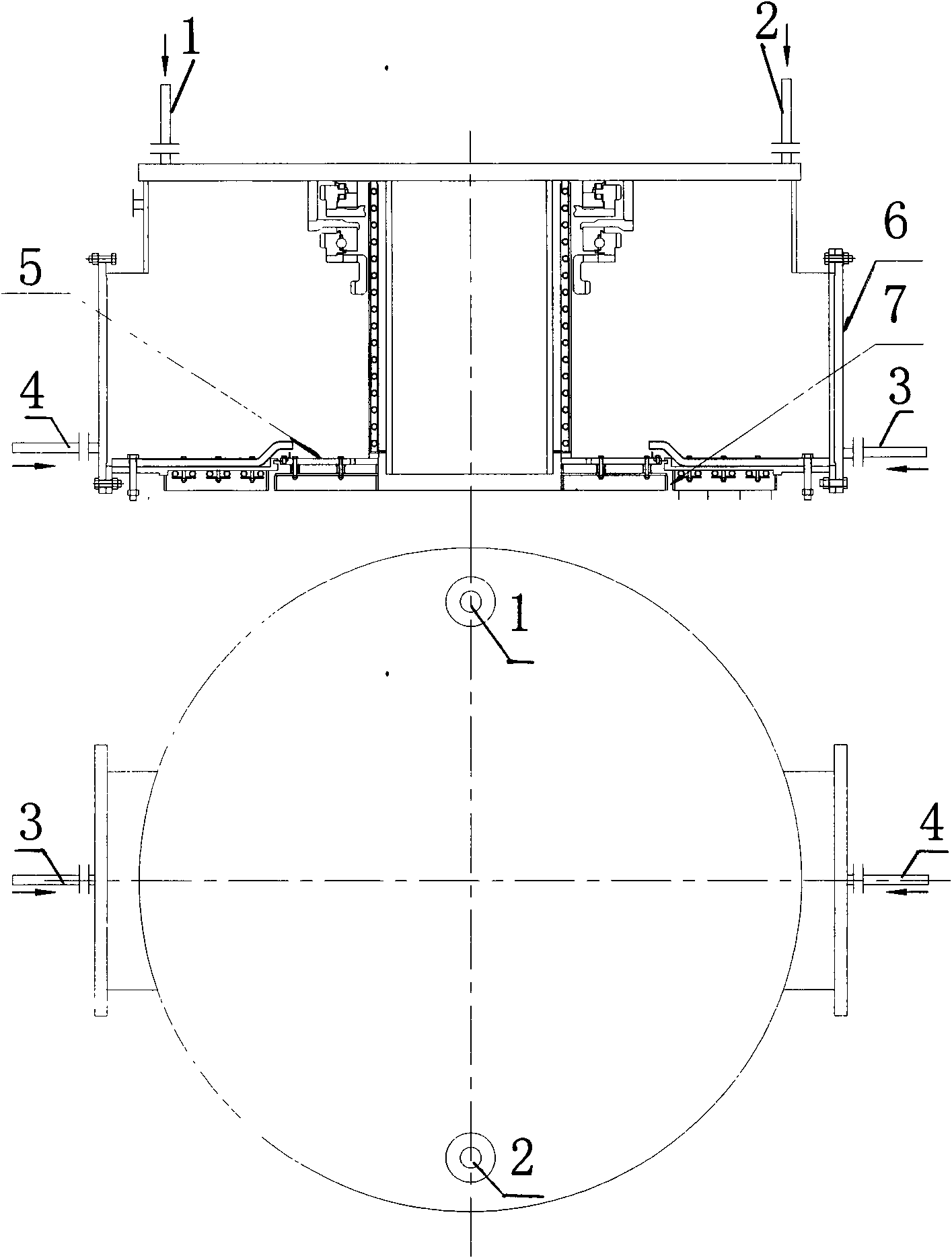
technical field [0001] The invention relates to a sealing and dustproofing method and device for an airtight box at the bellless top of an ironmaking blast furnace. Background technique [0002] In the field of metallurgy, the top airtight box of the ironmaking blast furnace is the key equipment to realize the rotation and swing distribution of the blast furnace, and its operation status directly affects the production of the blast furnace. Bellless top airtight box is widely used because of its compact structure and light weight. The cooling and sealing of the airtight box are two key links related to the stable operation of the equipment. The cooling of the airtight box adopts the demineralized water closed circulation method, and the sealing of the airtight box adopts nitrogen positive pressure to open the furnace. The existing technology of airtight box sealing is to set 4 purge points on the airtight box body, two on the upper part and two on the lower part, which are ...

Claims


Application Information

Patent Timeline
Patent Type & Authority Applications(China)
IPC IPC(8): C21B7/18
Inventor 李纲亓玉敏廉波
Owner SHANDONG IRON & STEEL CO LTD
Learn More