Eureka AIR delivers breakthrough ideas for toughest innovation challenges, trusted by R&D personnel around the world.

Reformer system, fuel cell system, and their operation method

A fuel cell system and fuel cell technology, which can be used in fuel cells, fuel cell additives, solid electrolyte fuel cells, etc., and can solve problems such as complex structures

Active Publication Date: 2009-12-23
KYOCERA CORP
View PDF1 Cites 4 Cited by
  • Summary
  • Abstract
  • Description
  • Claims
  • Application Information

AI Technical Summary

Problems solved by technology

[0004] However, in the conventional fuel cell system as described above, since it is necessary to install a liquid nitrogen storage tank and fuel electrode nitrogen supply equipment, the structure is complicated.

Method used


Image

  • Reformer system, fuel cell system, and their operation method
  • Reformer system, fuel cell system, and their operation method
  • Reformer system, fuel cell system, and their operation method

Examples


Embodiment Construction

[0033] Hereinafter, preferred embodiments of the present invention will be described in detail with reference to the drawings.

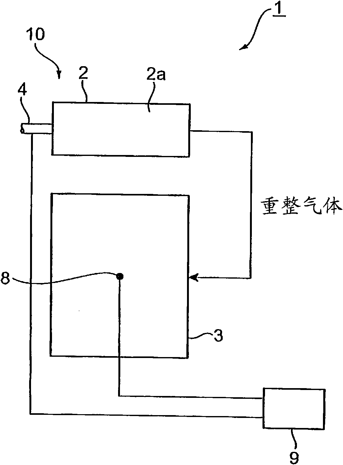
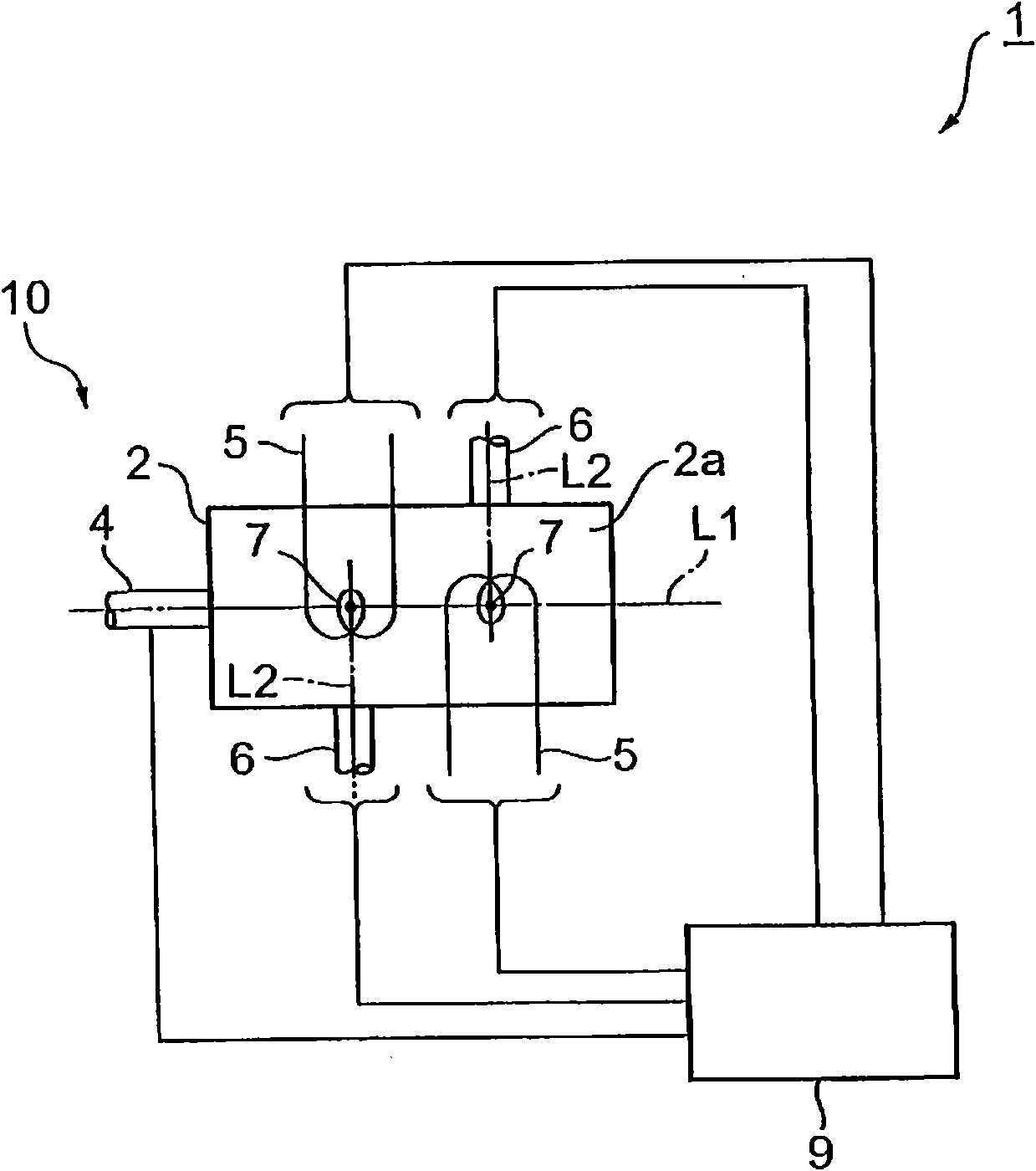
[0034] Such as figure 1 and figure 2 As shown, a fuel cell system 1 includes a reformer 2 that generates a reformed gas by reforming a raw fuel with a reforming catalyst 2a, and a solid oxide fuel cell 3 that uses the reformed gas as fuel.

[0035] The reformer 2 uses the reforming catalyst 2a to cause a steam reforming reaction between raw fuel and water vapor (water) to generate a hydrogen-containing reformed gas. Since the steam reforming reaction is an endothermic reaction, the reformer 2 utilizes the exhaust heat of the fuel cell 3 for the steam reforming reaction. As the reforming catalyst 2a, a catalyst known as a steam reforming catalyst can be used. That is, examples of steam reforming catalysts include ruthenium-based catalysts and nickel-based catalysts.

[0036] As the raw fuel, the raw material of the reformed gas can be a hydrocarb...


PUM


Abstract

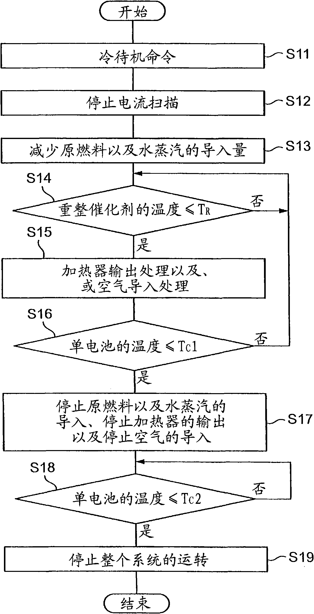
In fuel cell system 1, at the stop of power generation in fuel cell 3, the amount of a source fuel introduced to a reforming catalyst 2a of a reformer 2 is reduced, but at this time, before the temperature of the reforming catalyst 2a falls to an unreformed gas generation temperature, air is introduced to the reforming catalyst 2a to raise the temperature of the reforming catalyst 2a. At this time, before the temperature of the reforming catalyst 2a falls to an unreformed gas generation temperature, at least one of heating the reforming catalyst 2a and introducing air into the reforming catalyst 2a is performed. This raises the temperature of the reforming catalyst 2a and therefore, the generation of the unreformed gas is prevented and the reformed gas is supplied to the fuel cell 3, at the stop of power generation in the fuel cell 3.

Description

technical field [0001] The present invention relates to a reformer system having a reformer that generates reformed gas by reforming raw fuel using a reforming catalyst, a fuel cell system further having a solid oxide fuel cell that uses the reformed gas as fuel, and its Operation method. Background technique [0002] As a conventional fuel cell system, it is known to have a fuel electrode nitrogen supply device that supplies nitrogen stored in a liquid nitrogen storage tank to a fuel electrode of a fuel cell when power generation is stopped in a solid oxide fuel cell (for example, refer to Patent No. Literature 1). With such a fuel cell system, when power generation is stopped in a solid oxide fuel cell, nickel, etc. used in the fuel electrode in the fuel cell can be prevented from oxidative expansion, and as a result, electrolytes containing yttria-stabilized zirconia, etc., can be avoided Breakage occurred. [0003] Patent Document 1: Japanese Patent Laid-Open No. 2004...

Claims


Application Information

Patent Timeline
Patent Type & Authority Applications(China)
IPC IPC(8): H01M8/06H01M8/04H01M8/12C01B3/38
CPCC01B2203/1623H01M8/04022C01B2203/1047C01B3/384H01M8/04223C01B2203/1229H01M8/04955H01M8/04373H01M8/0612H01M8/04365C01B2203/169Y02E60/50C01B3/382H01M8/04776C01B2203/1223C01B2203/066C01B2203/1241H01M8/04738C01B2203/0805C01B2203/1247C01B2203/1619C01B2203/0244C01B2203/1058C01B2203/0233H01M8/04303H01M8/2425H01M8/04228H01M8/2457H01M8/04H01M8/06C01B3/38
Inventor 石田友孝
Owner KYOCERA CORP
Why Eureka
Eureka Blog
Learn More