Uninterrupted power supply system
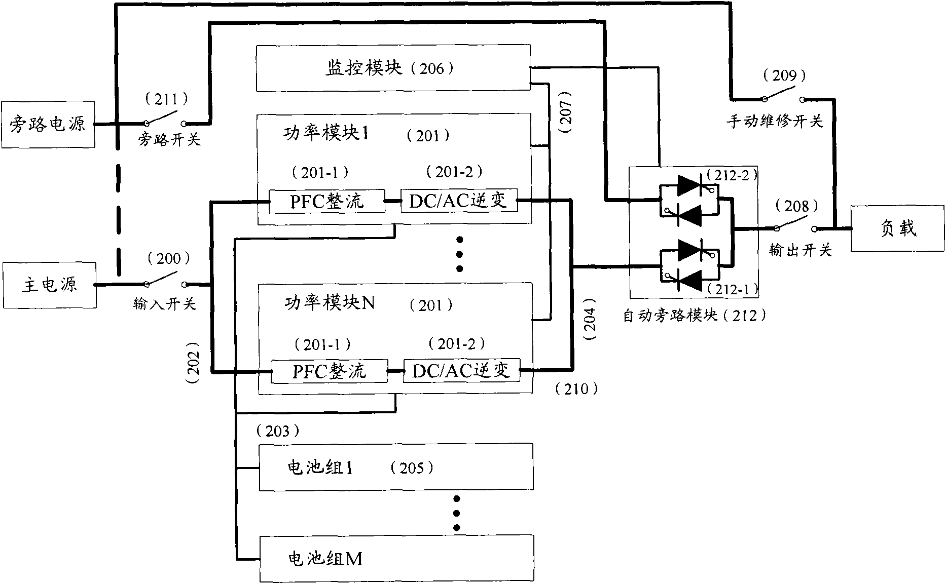
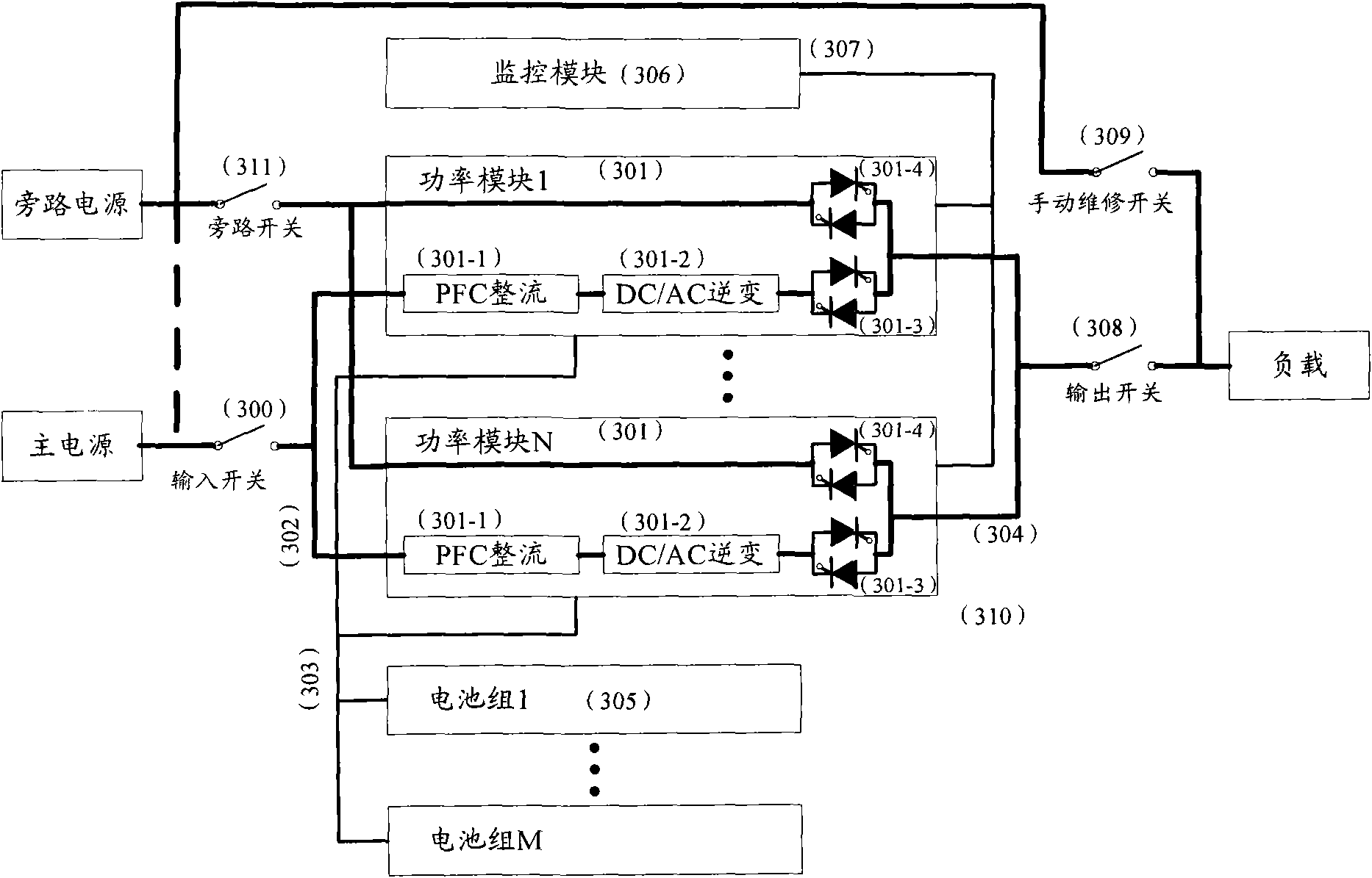
A technology of power supply system and power supply, applied in the direction of collectors, electric vehicles, electrical components, etc., can solve the problems of increased circuit loss, increased system failure rate, increased cost, etc., and achieves the effect of reducing loss and cost, and reducing system failure rate.
- Summary
- Abstract
- Description
- Claims
- Application Information
AI Technical Summary
Problems solved by technology
Method used
Image
Examples
example 1
[0071] Figure 5 It is a structural block diagram of the UPS system according to Example 1 of the present invention, as Figure 5 As shown, the system includes an input switch 400, at least two power modules 401, an AC input bus 402, a DC bus 403, an AC output bus 404, a battery pack 405, a monitoring module 406, a communication control cable 407, an output switch 408, and manual maintenance switch 409 . In addition, the system also includes a system rack capable of installing the above-mentioned modules, bus cables and switches.
[0072] The power module in this example consists of a PFC rectifier and a DC / AC inverter. The PFC rectifier is both a rectifier and a charger. The input point A of the PFC rectifier is alternating current, and the output point B is direct current. The direct current not only provides DC power for the rear inverter, but also provides charging for the battery pack. DC / AC inverter, the input end is connected to the DC bus point B, and the output end...
example 2
[0076] Figure 6 It is the structural block diagram of the UPS system according to the example 2 of the present invention, as Figure 6 As shown, the modular UPS system without an automatic bypass switch includes an input switch 400, at least two power modules 401, an AC input bus 402, a DC bus 403, an AC output bus 404, a battery pack 405, a monitoring module 406, a communication control Cable 407, output switch 408, manual maintenance switch 409. In addition, the system also includes a system rack capable of installing the above-mentioned modules, bus cables and switches.
[0077]The power module in this example consists of a PFC rectifier 401-1, a DC / AC inverter 401-2, an AC / DC or DC / DC charger 601-3, and a DC / DC transformer circuit 601-4. The PFC rectifier and charging device separately. The input point A of the PFC rectifier is connected to the AC input bus, and the output is a DC voltage point B, which provides DC power for the subsequent inverter. DC / AC inverter, th...
Embodiment 3
[0082] Figure 7 It is the structural block diagram of the UPS system according to the example 3 of the present invention, as Figure 7 As shown, the power module 401 in the third example consists of a PFC&DC / DC rectifier part 701-1, a DC / AC inverter part 701-2 and a charger 701-3. When the input main power supply is normal, the PFC&DC / DC rectifier converts the AC power into DC power, and at the same time has the function of increasing the input power factor and reducing the harmonics of the input current; the DC / AC inverter inverts the DC power of the previous circuit into AC output ; At this time, the input of the charger is connected to the DC voltage point B to charge the battery pack. When the input main power supply is abnormal, the direct current of the battery pack will obtain the direct current required by the subsequent inverter through the PFC&DC / DC transformer circuit, and the inverter will invert the direct current into alternating current for output.
[0083] O...
PUM
 Abstract
Description
Claims
Application Information
 - R&D
- Intellectual Property
- Life Sciences
- Materials
- Tech Scout
- Unparalleled Data Quality
- Higher Quality Content
- 60% Fewer Hallucinations
Browse by: Latest US Patents, China's latest patents, Technical Efficacy Thesaurus, Application Domain, Technology Topic, Popular Technical Reports.
© 2025 PatSnap. All rights reserved.Legal|Privacy policy|Modern Slavery Act Transparency Statement|Sitemap|About US| Contact US: help@patsnap.com


