
Micro-reflection liquid crystal display

A liquid crystal display, micro-reflection technology, applied in the direction of instruments, nonlinear optics, optics, etc., can solve the problems of poor reflection contrast and reflectivity, image parallax, etc., achieve the best contrast and reflection effect, reduce the manufacturing process, and weaken the reflection intensity Effect

Inactive Publication Date: 2009-12-16
WINTEK CORP
View PDF2 Cites 6 Cited by
  • Summary
  • Abstract
  • Description
  • Claims
  • Application Information

AI Technical Summary

Problems solved by technology

However, this design structure tends to cause parallax in the displayed image in reflective mode, and its reflective contrast and reflectivity are not good.

Method used


Image

  • Micro-reflection liquid crystal display
  • Micro-reflection liquid crystal display
  • Micro-reflection liquid crystal display

Examples


Embodiment Construction

[0027] In order to have a further understanding of the purpose, structure, features and functions of the present invention, the detailed description is as follows in conjunction with the embodiments. The above descriptions about the contents of the present invention and the following descriptions of the embodiments are used to demonstrate and explain the principle of the present invention, and provide further explanation of the scope of the claims of the present invention.

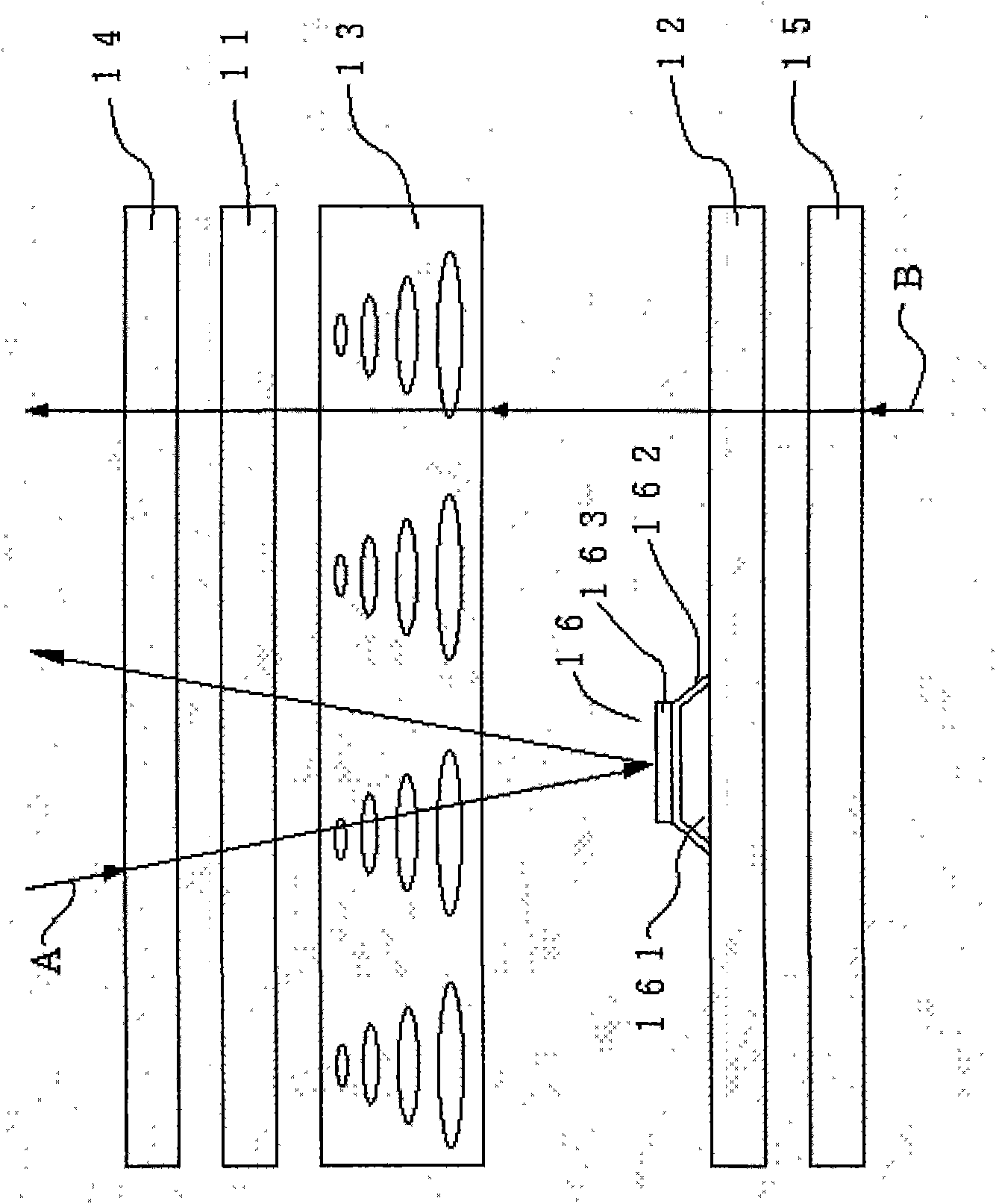
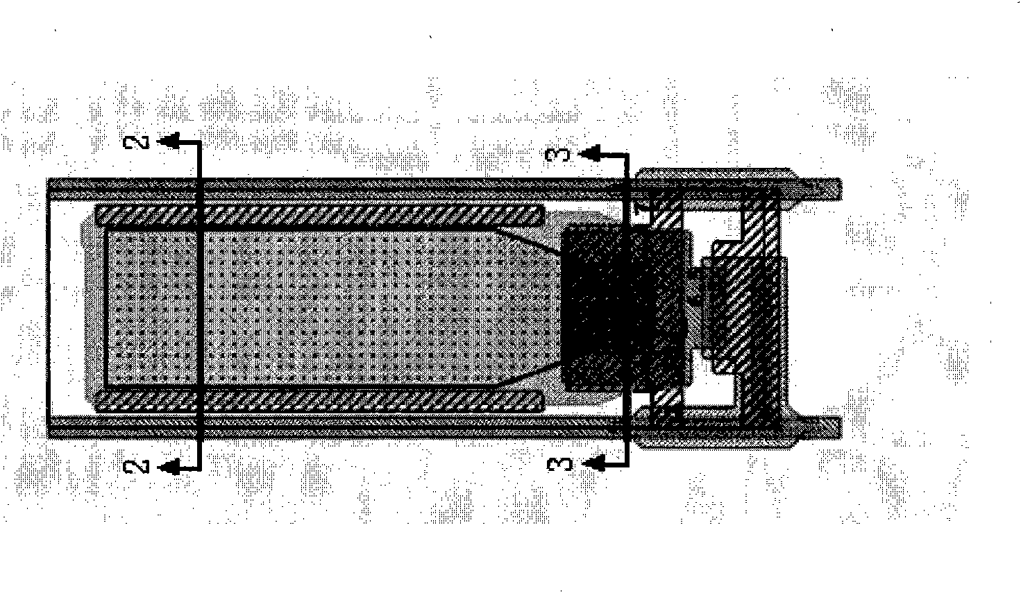
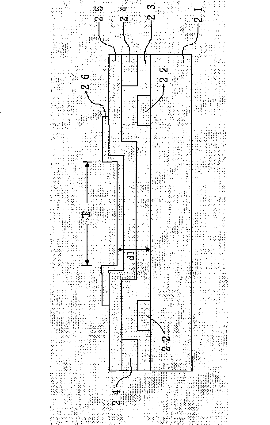
[0028] see figure 2 , which is a top view of a preferred embodiment of the sub-pixel structure of the present invention, showing a schematic structure of each sub-pixel. in accordance with figure 2 Sectional lines 2-2 and 3-3 in , can obtain the cross-sectional views of the reflective area R and the transmissive area T respectively, please refer to image 3 and Figure 4 . exist image 3 Among them, the penetrating region T is between the two metal plates 22 and the light can pass through the glass ...


PUM

PropertyMeasurementUnit
hysteresis lossaaaaaaaaaa

Abstract

The invention relates to a micro-reflection liquid crystal display. A break difference existing in the prior processing procedure of the prior TFT-LCD Array substrate and two optical compensation films which are perpendicular up and down on an optical slow axis are mainly utilized to clamp a liquid crystal box; and the most suitable phase difference value in a perpendicular polarizer compensation system is obtained by the axial difference between the optical slow axis of the optical compensation films and a long liquid crystal shaft and is matched with the starting and the closing of a liquid crystal voltage to achieve the display functions of the best dark state and the best bright state. Meanwhile, the best dark state can be obtained by the same driving voltage in a reflection mode or a penetration mode, and the favorable comparison and reflection effects can be achieved without adding processing procedures.

Description

technical field [0001] The present invention relates to a micro-reflection liquid crystal display, especially a liquid crystal cell that utilizes the gap and parallel arrangement existing in the existing five-way manufacturing process of the TFT-LCD Array substrate, and is matched with upper and lower optical The difference between the optical slow axis (slow axis) of the compensation film and the long axis of the liquid crystal is optically compensated for the micro-reflection effect of the liquid crystal display. Background technique [0002] Traditional transmissive thin film transistor liquid crystal display (TFT-LCD, Thin-Film TransistorLCD) such as figure 1 As shown, its structure is that a liquid crystal layer 13 is arranged between the upper substrate 11 and the lower substrate 12, and an upper polarizer 14 and a lower polarizer 15 are respectively arranged corresponding to the upper substrate 11 and the lower substrate 12, and the lower polarizer 15 A backlight sou...

Claims


Application Information

Patent Timeline
Patent Type & Authority Applications(China)
IPC IPC(8): G02F1/13363G02F1/1335
Inventor 吴易骏纪俊吉胡中惠
Owner WINTEK CORP
Learn More